Clearing Up Neutral-to-Ground Voltage Confusion
Power quality questions continue to revolve around one underlying issue related to electronic equipment: its ability to withstand the effects of electrical interference. If equipment sensitivity was always well known and defined, then we would have few, if any, doubts. In this perfect world, we would also know with a high degree of certainty that a voltage sag of a known amplitude and duration would have either no effect or a significant impact on equipment. Unfortunately, we seldom are privy to such information. Therefore, the possible effects of neutral-to-ground (N-G) voltage are often left up in the air.
When you measure N-G voltage, the measurement yields a simple voltage differential, which a voltage potential on either the neutral conductor or grounding conductor may create. Furthermore, this differential may be a simple by-product of neutral return current — or may even be part of a complex common-mode voltage signal. The effects of these conditions vary greatly.
The simple question — “What is the effect of N-G voltage?” — isn't so simple because it depends upon the magnitude, mode of propagation, timing, energy/frequency content, and sensitivity of the equipment involved. Let's try to resolve this important and confusing question.
Voltage drop and the NEC
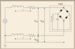
Figure 1 shows a simple diagram of a single-phase load connected to a voltage source. As the load draws current, a voltage drop develops across the supply and return conductors. N-G voltage measurements at the load will reflect the voltage drop across the return (neutral) conductor.
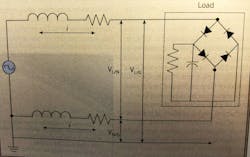
The National Electrical Code, in Sec. 210.19(A), FPN No.4, states: “Conductors for branch circuits as defined in Art. 100, sized to prevent a voltage drop exceeding 3% at the farthest outlet of power, heating, and lighting loads, or combination of such loads, and where the maximum total voltage drop on both feeders and branch circuits to the farthest outlet does not exceed 5%, provide reasonable efficiency of operation.” This amounts to a 6V drop in a 120V branch-circuit home run. Assuming equal losses in the supply and return conductors, then you should see an N-G voltage of 3V, which is a realistic condition.
Origins of required low N-G voltages
Some equipment installation specifications list extremely small values for acceptable N-G voltage, such as 0.5V to 1.0V. To meet these stringent requirements, you would usually install a dedicated transformer at the load, and/or run large gage wiring directly from the source N-G bond to the load.
Where did these extremely tight N-G voltage specifications come from? There could be a bit of hyperbole in these specifications, but there are some realistic origins. For instance, in the early 1980s, some equipment manufacturers installed power supply and motherboard grounding in configurations that made them extremely susceptible to earth/ground-referenced offset. In response, a few surge suppressor manufacturers introduced TVSS products with N-G components and extremely low transient voltage clamping levels — with disastrous consequences in certain cases. However, over time those design deficiencies were corrected — present-day test requirements usually prevent the wide-scale introduction of such products.
Figure 2 shows the basic diagram of a power supply system. What possible effect could neutral return losses have upon a system with this configuration? After all, there are no ground-referenced components on the input to the power supply that a voltage potential on the neutral conductor could upset. In fact, UL power supply tests reverse the polarity of voltages applied to a power supply. Consequently, the power supply must withstand 120V with respect to earth/ground for both normal and reverse polarities.
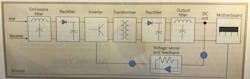
The voltage sensing and feedback circuitry also must meet electrical isolation requirements for safety purposes. The bond between the grounding of the system and the electronics occurs on the secondary of the high-frequency transformer inside the power supply or system. If the system is well designed, the effects of low-frequency voltage potentials appearing on the neutral conductor should have no adverse effects. In fact, if a power supply has a switched input capability (e.g., 85VAC to 264VAC), how could any simple N-G potential cause a problem? For example, suppose the power supply operates from a 208VAC source. Then each conductor on the input (L1 and L2) will have a 120V potential with respect to ground.
Determining equipment sensitivity to N-G voltages
Tests performed in the past by PowerCET, Santa Clara, Calif., to determine sensitivity of equipment to the effects of N-G voltage have never established any consistent results. In one series of tests, the staff deliberately created N-G voltages at the input to a mainframe computer and found that N-G voltages as high as 30VAC created no adverse effects.
There are two system configurations that can make equipment very susceptible to the effects of N-G potential:
- If the voltage sensing circuitry on the output of the power supply is referenced to the chassis of the equipment, but the bond from the DC return to the chassis is absent, then any small amount of earth/ground-referenced offset potential may appear as DC bus fluctuation, resulting in equipment malfunction.
- A more common problem develops when the power supply and circuit boards are floated (no intentional connection to chassis), but the device has RS-232 circuitry with internal referencing to ground. Earth/ground-referenced offset potentials may then cause erratic data transfer. Also, large common-mode potentials can degrade or damage the chip. The latter problem appears more frequently at printers and ancillary equipment.
While the industry has focused much attention on power frequency voltages measured with a voltmeter and involving N-G voltages, a much larger problem arises when you consider higher frequency N-G voltages that require measurement with better instrumentation. This poses realistic performance challenges for electronic equipment.
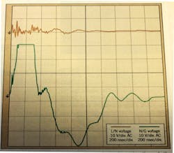
Figure 3 shows an example of true common-mode interference, which was recorded with a power monitor. The red trace is line-to-ground (L-G), and the blue trace is N-G. The earth/ground-referenced potential is common to both current-carrying conductors, and the only path for this interference is through earth/ground-referenced circuitry within equipment powered from that circuit. The common-mode potential is only about 50V to 70V, but the frequency content of this potential is fairly high (approximately 20kHz). The negative effects of these interference signals can range from power supply reset to damaged I/O ports (RS-232).
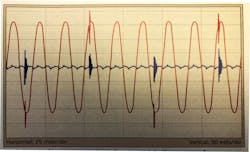
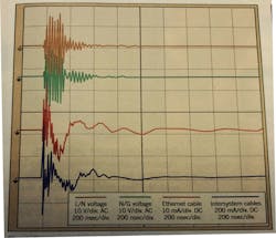
Figure 4 shows another example of a form of true common-mode interference signal. Here, PowerCET recorded L-N and N-G voltages with a line decoupler and recorded the resulting current signals in Ethernet cabling with Channels 3 and 4 with high-frequency current probes. The common-mode interference signal drives interference currents through the Ethernet and associated intersystem cabling.
If the staff was to measure only from neutral to ground, then the true common-mode nature of these signals would not be apparent. For instance, referring back to Fig. 1, the impedance of the neutral conductor will support impulse propagation as loads cycle on and off. The resulting transient voltages, however, are developed from a relatively high impedance. Therefore, their potential to wreak havoc is limited. In comparison, common-mode interference signals, as shown in Figs. 3 and 4, not only have more available paths through the system, but their energy and frequency content may be higher.
What about current flowing through earth/ground that is measured as an N-G signal? Figure 5 shows an event caused by current surging through the grounding system of a facility. The N-G voltage waveform truncates at 40V peak because the waveform exceeded the input range of the digital storage oscilloscope. However, you can follow the slope of the lines and extrapolate that the peak voltage easily reached and probably exceeded 100V! This event caused hard drive failures and data loss.
Applying what we've learned
As many power monitor setups do not use L-G connections along with L-N and N-G connections, you must ferret out true common-mode events. With sole usage of N-G connections to detect common-mode events, you may develop a tendency to ignore low amplitude N-G transients. After all, if recorded transients are always present at a given level and you can determine no adverse effects, why waste monitor memory recording those events? Increasing the monitor threshold to avoid capturing lower level and commonly occurring N-G events may leave the true common-mode events undetected.
We can sum up our experiences as follows:
- N-G voltages less than 3V and developed at power frequencies seldom cause adverse effects.
- Low level N-G transients less than 25V peak and caused by load cycling usually do not cause adverse effects. However, the potential for adverse effect will increase as frequency content and amplitude increases.
- Higher frequency, true common-mode events can cause adverse effects, but you may not be able to detect or correctly identify their presence.
- Measuring N-G voltages with a multimeter is a valid procedure, and the measurements you make may help identify wiring problems that cause excessive voltage drop. Remember, high levels of N-G voltage invariably arise from grounding/bonding problems.
Shaughnessy is vice president, PowerCET Corp., Santa Clara, Calif.