The Basics of Variable-Frequency Drives
When Tesla first introduced the 3-phase alternating current (AC) induction motor in 1888, he knew that his invention was more efficient and reliable than Edison's direct current (DC) motor. However, AC motor speed control requires either varying the magnetic flux or changing the number of poles on the motor. Even decades after the induction motor gained widespread use, changing the frequency for speed control remained an extremely difficult task — and the physical construction of the motor prevented manufacturers from creating motors with more than two speeds.
As a result, DC motors were necessary where accurate speed control and significant power output were required. In contrast to AC motor speed control requirements, DC motor speed control was achieved by inserting a rheostat into the low-power DC field circuit, which was feasible with available technology. These simple motor controls varied the speed and torque, and were the most economical way to do so for a number of decades.
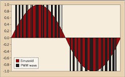
Fig. 1. An ideal sinuosoid and PWM waveform figure.
By the 1980s, AC motor drive technology became reliable and inexpensive enough to compete with traditional DC motor control. These variable-frequency drives (VFDs) accurately control the speed of standard AC induction or synchronous motors. With VFDs, speed control with full torque is achieved from 0 rpm through the maximum rated speed and, if required, above the rated speed at reduced torque. VFDs manipulate the frequency of their output by rectifying an incoming AC current into DC, and then using voltage pulse-width modulation to recreate an AC current and voltage output waveform. However, this frequency conversion process causes 2% to 3% loss as heat in the VFD — caloric energy that must be dissipated. The process also yields overvoltage spikes and harmonic current distortions.
Variable-frequency types
There are three common types of VFDs. Current source inversion (CSI) has been successfully used in signal processing and industrial power applications. CSI VFDs are the only type that has regenerative power capability. In other words, they can absorb power flow back from the motor into the power supply. CSI VFDs give a very clean current waveform but require large, expensive inductors in their construction and cause cogging (pulsating movement during rotation) below 6 Hz.
Voltage source inversion (VSI) drives have poor power factor, can cause motor cogging below 6 Hz, and are non-regenerative. Consequently, CSI and VSI drives have not been widely used.
Pulse-width modulation (PWM) VFDs are most commonly used in industry because of excellent input power factor due to fixed DC bus voltage, no motor cogging, higher efficiencies, and lower cost. A PWM VFD uses a series of voltage pulses of different lengths to simulate a sinusoidal wave (Fig. 1 on page 8). Ideally, the pulses are timed so that the time average integral of the drive yields a perfect sinusoid. The current method of choice to produce this waveform runs a triangle wave and sine wave through a comparator, and outputs a voltage pulse whenever the sine wave's value is greater than the triangle wave. The current electric component of choice to generate the voltage pulse is the insulated gate bipolar transistor (IGBT), although silicon-controlled rectifiers (SCRs) can work as well. In the near future, injection-enhanced gate transistors (IEGTs) will be used to perform this task. Much more long term, memristors will probably become the component of choice for this task.
Memristors are the fourth passive circuit element, linking electric charge and magnetic flux. Memristors have been hypothesized to exist for more than 30 years, but were not fabricated until April 2008 by Hewlett Packard Labs. Hewlett Packard hopes to use these devices as a passive transistor, reducing their heat generation compared to other types of memory. Regardless of the component used to form the sine wave, the switching action causes problems.
Heat, power losses, and harmonics
The first problem a VFD manufacturer needs to address is heat. Although VFDs are highly efficient devices, manufacturers are unable to produce an ideal set of components. The heat lost in the drive is governed by the following equation:
Hloss = Pt (1-η)
Where Hloss is the power lost (W), Pt is the power through the drive (W), and η is the efficiency of the drive. Usually, VFDs have an efficiency rating between 95% and 98%. This means the amount of air that must be moved through the drive is governed by the equation:
m = Hloss÷(CpΔT) = Pt(1-η)÷(CpΔT)
Where m is the mass flow rate (kg/s), Cp is the specific heat of air [kJ÷(kg×K)], and ΔT is the difference in temperature between the incoming air and the outgoing air (K). This heat can cause significant cooling costs to be added into the design, especially if the drive is unable to be placed in an unclassified location (area free of flammable gases or particles). If the drive must be placed in a classified location, then the airflow going to the drive will need to be purged and pressurized.
Fig. 2. A real sinusoid and PWM waveform. Note how the harmonics affect the shape of the sinusoid.
Heating is only one of the problems with VFDs. The other major problem lies with system harmonics. A picture of the PWM and the harmonics they cause is shown in Fig. 2. The irregularities in the sine wave are called harmonics. In an ideal power circuit world, these harmonics should not exist. They do nothing but cause problems. Fortunately, there are a number of ways to mitigate harmonics.
One of the simplest methods of dealing with harmonics is to place a sine wave filter on either side of the VFD. On the line side, these are typically called line reactors and have reactance values anywhere between 1.5% and 5.0% impedance. Higher impedance not only stops more harmonics, but it also limits the power going to the VFD.
Another tactic that can be used on the line side of the VFD is to place capacitors at a common bus. Because the impedance of a capacitor is inversely proportional to the frequency of a signal, the harmonics see a short through the capacitor and travel through the capacitor to ground, hopefully ignoring the other loads on the bus. VFDs may also use an active front end to limit the harmonics that the line side sees. An active front end has another IGBT switching at an inverse voltage as the main IGBT, but it is placed through a high pass filter so that the fundamental power signal goes to ground. The summation of the two harmonic signals ideally should be zero. If an active front-end drive is not suitable for some reason, a passive front-end VFD might be procured. Passive front-end VFDs use multiple phase-shifting transformers and diode bridges to mitigate harmonics.
The more pulses a passive front-end VFD has, the fewer problems with harmonics exist. The trade-off is that the line voltages must be well balanced, and with each additional phase shifting transformer there is increased cost and a loss in efficiency. In extreme cases, an isolation transformer might be procured. Although this is one of the most effective ways to prevent harmonics from spreading, it's also one of the most costly.
If harmonics are not sufficiently mitigated on the line side of the VFD, crosstalk and overheating could become issues. Overheating could either cause bus sizes to be derated or increase cooling costs. Crosstalk is defined as the signal from one circuit interfering with another circuit. Generally speaking, it is a larger issue than overheating. An example of this is a radio just slightly out of tune. Although it is possible to hear the music through the static, the static is annoying. Crosstalk is an annoying thing in telecommunication circuits. In power circuitry, crosstalk will cause overheating and frequency relay trips.
Just as harmonics left unchecked on the line side can cause problems, they can create issues on the load side as well. This is because of the nature of waves. For example, a small force exerted on a Slinky at either end will cause a high amplitude sine wave. Electromagnetic waves act in the same fashion, meaning a small amount of reactance can cause large voltage spikes. Because this reactance is inductive in nature, most output filters are capacitors connected in a delta configuration. Ideally, this should make the reactance portion of the impedance go to zero. If the impedance is matched properly, then this does not occur.
A note of caution: Capacitors connected on the load side of the VFD can create a large number of problems, up to and including destroying a drive. Therefore, it's wise to check with the drive manufacturer before installing a sine wave filter on the load side of the VFD. On rare occasions, an active filter may be used. Although these tend to work well, they are rather expensive and usually have to be custom designed.
VFD benefits
Despite the fact that VFDs generate a large amount of harmonics and heat, they would not be as widely used and popular as they are today if they did not have significant economic benefits.
Electrically, VFDs run at a high power factor. Any class of induction motors usually has a low power factor at half and three-quarters load (0.75 to 0.85). This actually decreases the life of the motor, because the unnecessary increase in current overheating the winding insulation. VFDs bypass this problem by running the load at a frequency below the fundamental.
The most obvious reason to procure a VFD is speed control. This is usually done for process, operation, and economic benefits. One economic benefit comes from the reduction of maintenance when using a VFD, especially not having to deal with the DC motor carbon brushes or mechanical speed-control gearboxes (transmissions). The most obvious economic benefits of VFDs occur with fans and pumps. The power that a pump or fan consumes is directly proportional to the cube of the velocity. This means if an operator can run a fan at 80% of full speed, it theoretically uses 51% of full load power.
VFDs also optimize motor starting characteristics. VFDs bring motors up to full speed quickly and by drawing only 100% to 150% of full load amps (FLAs). This ability to start at normal FLA is very important if the power supply cannot withstand the normally six times FLA across-the-line starting draw, or even the 350% FLA soft-start device current. VFDs do this by managing the magnetic flux of an induction motor. Magnetic flux is directly proportional to the voltage and inversely proportional to the frequency. By keeping the flux constant, the inrush current does not exceed the FLA rating of the motor, and full torque is maintained. This is a significant improvement on a soft-start, which has significant voltage drop problems and cannot start under full load.
Another potentially useful aspect of VFDs is demonstrated in Fig. 3, (click here to see Fig. 3) which shows the output of a constant torque VFD. Notice the two regions, constant torque, and constant horsepower. The constant torque region is fairly self explanatory; the VFD is regulating the flux so that the current is constant. Once the VFD surpasses the rated system frequency, the voltage cannot increase due to the physical constraints of the system. Because the voltage is static — and the frequency is increasing — the flux is forced to decrease. When this occurs, the current and torque are forced to decrease as well. This is called field weakening. Although not necessarily a good thing, it can be useful if there is a need to power a partial torque load above the rated speed. In addition to this capability, VFDs can also take any form of input power whether it's single-phase AC, 3-phase AC, or DC. VFDs fed from a DC source still power an AC load without an internal rectifier.
VFDs also have some applications on the power grid. One classic example of this is a doubly fed induction generator, in which the VFD can force a fixed frequency and voltage signal out of a variable-speed (frequency) input. This is commonly seen in wind turbines and other small hydroelectric generation projects that will be connected to the power grid. Other renewable energy sources, such as photovoltaic cells, can use VFDs to act as an inverter before connecting to the power grid, although inverters with buck-boost technology are more common. While there are many potential uses for VFDs on the commercial power grid, they are beyond the scope of this article.
In summary, whenever a load has either a variable torque or a variable speed, a VFD should be considered. A VFD might be considered if a large motor has a problem with voltage drop, torque, or inrush current during start-up. Even though VFDs undoubtedly solve their fair amount of problems and provide substantial energy savings, the heat they generate must be dissipated — and the harmonics they produce must be mitigated.
Novak is an electrical engineer with Fluor, Inc., Sugar Land, Texas. He can be reached at [email protected].