The Basics of Current-Sensing Relays
A range of manufacturing and production processes rely on current-operated relays to provide a continuously adjustable trip-current setting. They are able to protect mechanical apparatus from jam-up or other overloading conditions that result in measurable increases in motor current. Functionally, they sense current levels and provide an output signal when a specified current level is reached. Current-sensing relays are used to:
- Signal high-current conditions, such as a clogged grinder.
- Identify low-current conditions, such as a pump that has encountered a low-water condition. Sense the current a motor is drawing to feed the current to a programmable logic controller (PLC).
To meet the unique requirements of a diverse set of applications, a wide range of devices and options is currently available to designers, installers, and maintenance professionals, including plug-in style, base-mounted, DIN-rail mount, and donut-style. These types of devices offer the following capabilities:
- Sensing both AC and DC current — from milliamperes to several amperes.
- Sensing thousands of AC amperes with a current transformer (CT).
- Current setpoints can be fixed or adjustable.
- Input AC or DC.
- Analog output — voltage or current — or contact closure.
- Self- or looped-power units.
- Fixed or adjustable internal time delays.
Protecting equipment from overcurrents
Crushers come in several forms and are used to reduce the size of materials. Typical applications include shredding wood as well as crushing rock, coal, and other minerals. They have electric motors sized to the capacity of the crusher. Material is usually fed to them by a conveyor at a rate that provides maximum production capacity and prevents overloading. In the event of an overload, a crusher can stall and jam, resulting in significant downtime to clean the material from the crusher and return it to operation.
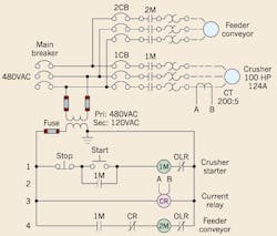
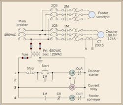
A current relay with overcurrent setpoint provides protection and enhanced functionality for machinery that may otherwise become overloaded. The circuit in Fig. 1 below illustrates the electrical arrangement to accomplish this design.
Fig. 1. The current relay with an overcurrent setpoint provides protection and enhanced functionality for this rock crushing equipment arrangement.
Material is fed to the crusher by the feeder conveyor, which can overload the crusher with excess material. The crusher starter’s overload relay could be used to protect the motor from overloading, but the operation would prove inefficient. The overload relay would trip the starter off, and then personnel would need to first wait for the overload relay to cool, then reset the overload relay, and finally restart the motor. In addition, tripping of the relay would cause the crusher to stop with a full load of material, resulting in the lost production time needed to remove the material from the crusher.
With a current-sensing relay (CR), the operation of the crusher can be improved. In this case, when the crusher motor becomes overloaded, CR’s setpoint is exceeded, and 2M (the feeder conveyor’s starter) is temporarily de-energized. When the crusher processes the material, the current level drops, and CR restarts the feeder conveyor. An adjustable time delay relay is sometimes included in this control scheme to delay the restart and allow the material to be cleared from the crusher. The time delay may be included in the overcurrent relay or as a separate device. The same circuit could be used for other applications as well. Coal needs to be washed before it can be pulverized and burned. After washing, it must be dried. A centrifuge (similar to a clothes washer in the spin-dry cycle) can be used for the purpose. A current relay can monitor current for the centrifuge to prevent overloading.
Safeguarding equipment from undercurrents
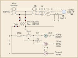
Cavitation is a destructive condition caused by the presence of bubbles that are formed when a centrifugal pump or vertical turbine pump operates with low liquid levels. The bubbles form and then burst, resulting in pitting and destruction of the impeller. A current-sensing relay in the circuit can prevent this from occurring (Fig. 2 below).
Fig. 2. The current-sensing relay in this water pump electrical circuit prevents the pump from running when the water level is too low.
When a pump is operated with a flooded suction and liquid completely covers its inlet, the pump’s motor will draw normal operating current. On the other hand, if the liquid level falls below the inlet, the pump’s motor will draw less current. The circuit in Fig. 2 operates as follows:
- Start button is depressed, causing starter M to energize.
- Simultaneously, time delay TD begins to time.
- Because CR is an undercurrent relay, its contact will not be closed when the motor is initially started.
- TD is used to short circuit CR’s normally open contact during starting.
- Current relay CR energizes when the motor’s current exceeds the low-current setting.
- TD’s normally closed contact opens after TD times out, enabling CR to protect the pump from a low-liquid situation.
- When the motor’s current falls below the setpoint, CR’s contacts open and de-energize M.
Note that the pump will not restart automatically, as the operator will have to assure that sufficient liquid is available before restarting.
This circuit can be used for pumps in fixed locations, such as high-service pumps used to fill a water tower, or where pit-pumps are used to pump water from pits in coal mines or quarries. In the latter case, the pumps are normally unattended. When the water level in the pit falls from the pumping action, the pump will shut off. An employee inspects the pumps periodically to check their status.
Preventing power outages from ground faults
Ground faults contribute to outages in industrial plants, especially further from the service equipment, and nearer to the point of use. While ground-fault protection is required by Sec. 230.95 of the 2011 NEC for solidly grounded wye services of more than 150V to ground, but not exceeding 600V phase-to-phase (we know them as 480/277V systems), it doesn’t require ground-fault protection downstream of that point (except in healthcare facilities). The maximum setting can’t exceed 1,200A, and the maximum time delay can’t exceed
1 sec. for ground-fault currents greater than 3,000A.
Ground-fault protection is installed to prevent arcing ground faults. While ground-fault protection only on the main breaker offers maximum protection for the electrical system, the entire building electrical system may be shut down due to a low-level ground fault and is not conducive to efficient production. Numerous large systems have been tripped out by a ground fault produced by an electrician’s having grounded a light switch inadvertently when working, which raises two cautions:
- De-energize circuits prior to performing work.
- Adjust ground-fault systems when installing equipment. Manufacturers ship equipment with settings at minimum.
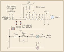
A better choice may be to provide low-level ground-fault protection on both individual motors and the main breaker. Figure 3 below illustrates a simple example of this design concept.
Fig. 3. In this type of electrical arrangement, both the low-level motors and the main breaker are equipped with ground fault protection.
In this example, the main breaker contains ground-fault protection within its trip unit. Ground-fault protection has now been added to a motor as well. Notice the three motor leads pass through the window of GFCT, a “donut-style” current transformer. Some ground-fault relays incorporate a CT in their construction while others may have it mounted separately, especially for larger motor leads.
GFCT is operating as a zero-sequence ground-fault detector. A zero-sequence CT operates by algebraically summing the currents through its core; that is, all current flowing out through the core must also return through the core. If a ground fault occurs on one of the conductors, part of the current returns to the source through the ground path. The difference will be detected by the ground-fault relay (GFR), which will have a setpoint. If the current exceeds the setpoint, GFR’s contacts on line 1 will open, de-energizing starter M and stopping the motor. When starting, some large motors can induce temporary ground-fault current into the electrical system during the starting surge. A ground-fault relay can incorporate a time delay to prevent tripping during this period.
Current transformers
Current transformers (CTs) are a special transformer that change current from one level to another for monitoring or measuring purposes. They typically have a one-turn primary. The cable whose current is to be measured is placed through the window, which is the primary turn. The secondary connection is made at the screw terminals.
CT current step-down ratios are represented as follows — primary current: secondary current. An example is a CT having a 1,200A primary and 5A secondary. Its ratio will be 1,200:5. A 5A secondary is a common secondary current. Some secondary currents are 1A, but those are not common.
The secondary for a CT should never be open-circuited when current is flowing through the primary. High voltages can be generated that can cause insulation breakdown and consequent destruction of the CT or shock/injury to the user. The secondary should be short circuited instead. Special shorting blocks are often employed on which the CT’s leads, and the leads for the load — relay or meter — are terminated. Shorting bars short circuit the leads so the CT’s load may be safely removed from the circuit for repair or calibration.
Current transformers are available with different window diameters. When specifying, make sure the window opening is adequate for the cables, especially if paralleled cables are used.
Bredhold is an application engineer with Eaton Corp., Louisville, Ky. He can be reached at [email protected].


