Sometimes the best way to describe how to analyze a communication cable common-mode (CM) noise problem is to describe an actual procedure. The following case history, which was provided by the late Warren Lewis, describes a communications cable signal problem and details the analytic procedure and diagnostic equipment he used in resolving the problem.
The “victim” cable was a 52-ohm coaxial RG-58/U cable approximately 50 feet long that ran from a transducer located in the field to a control room via an overhead PVC conduit. The transducer end was provided with a 2-wire-plus-ground connector and a switch mode power supply (SMPS) fed by a 120V branch circuit. The control-room end terminated with a BNC connector to a proprietary interface card on the back of a PC-type controller.
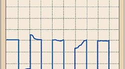
A preliminary measurement using a portable oscilloscope and a 10X voltage probe on Channel B showed a corrupted signal, similar to that shown in Fig. 1 on page 26, on the input to the cable end's receiver plug-in card. This badly corrupted square wave signal was about 1.8V peak-to-peak, with a typical period of about 2 milliseconds (500 Hz).
Troubleshooting procedure. The coaxial cable was removed from the controller end, and a BNC-type TEE fitting was attached in its place, as shown in Fig. 2. This allowed a tap to be made across a noninductive 50-ohm resistor, one end of which was soldered to the signal pin of one port of the TEE.
The first step was to see if any significant CM current, which could be correlated in some way to the corruption of the signal, existed on the victim coaxial cable itself. This was done by connecting a CT to a portable oscilloscope and then clamping the CT around the coaxial cable. Figure 3 shows the results of this test. The waveform looked familiar: It was the signature of a typical AC input current to an SMPS.
Next, we had to determine if this CM current had a timing relationship to the EMI on the victim cable's signal. This involved using the voltage probe between the TEE connection and the portable oscilloscope. This time, we used a two-channel setup so that we could view both CM current and data signal voltage simultaneously. The result is shown in Fig. 4. As you can see, a clear relationship existed between the EMI and CM current.
We next disconnected the TEE connection from the rear of the controller but left it attached to the B-channel voltage input on the portable oscilloscope. We wanted to see the result with the CM current path on the coaxial cable completely open at the receiver end. The result was the clean square wave shown in Fig. 5.
Now the question was “Where was the CM current getting onto the coaxial cable?” Still working toward a solution, we looked at the transducer end of the cable run. We disconnected the 120V power supply, reconnected the TEE fitting to the controller, and made another CM current measurement. We found no appreciable CM current.
We made one more test, this time placing the CT around the AC power supply cord for the SMPS to see if we could measure any CM current. We did find appreciable CM current and concluded that the SMPS was probably the aggressor source of EMI.
Bench tests. It was now time to pull out the SMPS and check it on the bench. We powered up the SMPS using the adapter shown in Fig. 6. This arrangement allowed the placement of a CT around any one or combination of the three AC line conductors used in the power cord.
We tested the equipment safety-grounding conductor (green wire) first by placing the CT around it and energizing the SMPS. Except for amplitude, our portable oscilloscope clearly showed a signature current waveform of the same shape and timing as we observed on the coaxial cable. This clearly was not a typically permitted small leakage current. Something was wrong inside the SMPS.
We next used a continuity tester to check from each unplugged SMPS line cord pin to the metal enclosure of the SMPS. This showed good continuity for the green wire, an open on the ungrounded side of the line (black wire), and a short on the grounded (neutral) side of the line (white wire).
Looking closer at the SMPS, we found a shorted AC line filter capacitor, which was connected between ground and neutral pin, as shown in Fig. 7. This resulted in some portion of the SMPS neutral current being divided between the neutral and equipment grounding paths, which consisted of the green wire and the grounded copper braid of the coaxial cable. The controller's input power cord provided the required connection back to the electrical system neutral of the transformer. We replaced the defective SMPS.
We still had one question left, “How did the ground-fault current flowing on the coaxial cable's braid combine with and corrupt the instrumentation signal?” This shouldn't happen when coaxial cable is used for signal transport.
The answer was that the data signal was very low frequency and flowed on the coaxial cable's braid and center conductor with very little skin effect. Without skin effect, both the desired signal current and undesired currents were free to flow in the entire available cross-sectional area of the braid, similar to DC. So, in effect, the currents shared the same conductor volume and algebraically added together to produce a voltage drop on the coaxial cable due to the braid's impedance. This, in turn, produced the combined signal voltage in the differential mode at the receiver end of the cable.
If the signal had been at a higher frequency, it would have flowed entirely on the inner surface of the braid, nearer the center conductor. This would have left a negligible amount of shared conductor volume in which the two currents could mix together.
Sidebar: Diagnostic Instruments to Make CM Measurements
Here's a listing of available diagnostic instruments and accessories you can use to detect the presence of common-mode (CM) current and analyze corrupted data signals.
Clamp-on CTs. These devices pick up CM current because this current generates a magnetic field around conductors that is proportional to the current's magnitude. Differential-mode (DM) currents, on the other hand, do not generate very much magnetic field, since the signal pair is physically configured so that the magnetic fields cancel each other out. This is called a zero-sequence magnetic field condition, which is a phenomenon familiar to electricians using clamp-on ammeters to gather all of a circuit's conductors through the ammeter's aperature at the same time. Here, any current displayed is called “unbalanced current” or “ground-leakage current,” depending on the situation. A CT can pick up the presence and magnitude of a CM current, but you also need an indicator. This is where an analog or digital meter comes in.
Analog and digital meters. Typically, if you're interested in only CM currents ranging from DC through about 25th or so harmonic (about 1.5kHz on a 60 Hz system), you can use a simple average-responding or true-rms type of analog or digital meter. These kinds of meters are quite useful in finding and tracking CM currents on data communication cables, where the problem can be related to the AC system's fundamental of the first few tens of harmonics. Such currents are common in most facilities and appear most often on cables that are suffering from conducted CM noise currents or from near-field magnetic field coupling.
Oscilloscopes. The above kinds of restricted-bandwidth detector/indicators are often not useful in finding interfering CM currents that range into the tens of kHz or well into the MHz region. Also, you may need more sensitivity than that provided by the typical meter to “see” the CM current. In this case, you could interface a CT with an oscilloscope to get a simultaneous display of a broad range of frequencies as well as lower level signals. This ability to see the CM current on the time-domain (x = time, y = amplitude) also helps visualize the CM current's signature, which can really help in identifying the CM current's source and in tracking the same CM current through several points of measurement.
Wide-band, lab-grade CTs. You would use these devices when you need to take measurements well into the MHz range, where the bandwidth is from around 1 kHz to over 150 MHz.
Hall-effect-based CTs. You would use these devices if the CM current is below a few Hz. A sensor of this type will simultaneously respond to DC and AC but may not be usable above about 100kHz. Also, these devices may be susceptible to external magnetic fields. The term “Hall effect,” in reference to conductors, is defined in the IEEE dictionary as “the change of the electric conduction caused by that component of the magnetic field vector normal to the current density vector, which, instead of being parallel to the electric field, forms an angle with it.”


