A busway is defined in Art. 368 of the 2014 National Electrical Code (NEC) as “a raceway consisting of a grounded metal enclosure containing factory-mounted, bare, or insulated conductors, which are usually copper or aluminum bars, rods, or tubes.” Being a raceway, it competes with other raceways, such as conduit with conductors, during the electrical design stage of buildings.
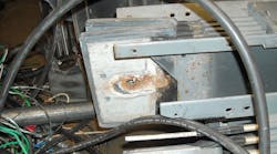
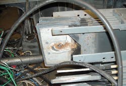
Many design engineers prefer to use busway in buildings. This is due to the large ampacities that can be carried through a relatively small cross-sectional area or floor penetration when run vertically in a pipe chase. When busway is used horizontally in an industrial application (Photo 1), it allows for a very flexible system to provide electrical drops from the ceiling to production equipment on the factory floor. Busway is typically sized in the 225A or higher range. This allows for many diverse loads to be connected with relocatable switch plugs without having to run new feeders or branch circuits every time a machine location changes.
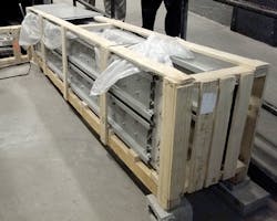
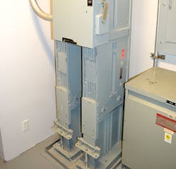
Although the initial material costs for a busway type system may be higher, there is a reduction in the labor cost to install these systems. Busway typically bolts together in manageable 10-ft sections (Photo 2). In addition, switch taps at each floor or machine are easily made from plug-in style busways. But once a busway system is installed, you can’t simply ignore it.
Busway needs maintenance
Conduit and wire raceway systems are relatively maintenance-free after installation. Conduit and wire can be run for very long distances before a splice or uninsulated conductor is encountered. Even though the conduit has a coupling at 10-ft intervals similar to the busway, the conductors are pulled in continuous lengths between distant junction boxes. In comparison to busway, there are no internally exposed, uninsulated, energized conductors at 10-ft intervals.
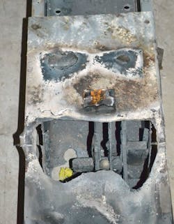
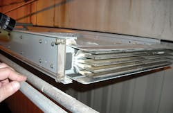
With busway, you can see there are many accessible points-of-entry into the raceway for liquid contaminants to penetrate and contact uninsulated, energized conductors. This is why it is important to prevent liquid spills near or onto busway. Liquid spills are especially disastrous when the liquid runs down a vertically installed busway in a multi-story building application (Photo 3). Because of these vulnerabilities, busway has maintenance requirements specified by the manufacturer and organizations such as the National Electrical Manufacturers Association (NEMA).
Arcing ground faults on busway, related to not following the manufacturer’s and NEMA’s maintenance recommendations, have resulted in huge property and electrical equipment losses. In addition, catastrophic business losses typically occur due to fire and sprinkler-water damage.
Reasons for concern
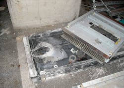
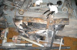
A recent analysis by Hartford Steam Boiler Inspection and Insurance Company indicates that there have been many failures of vertically run busway installations in multi-story buildings. Other horizontally run busways have also failed when subjected to long-term water or other contamination sources (Photo 4).
Section 368.12(D) of the NEC does not allow busway to be installed outdoors or in wet or damp locations unless identified for such use. When busway is specified and installed in an indoor vertical pipe-chase application, the assumption is that it will never be in a wet or damp location. Unfortunately, over the life of most buildings, other building systems fail and create damp or wet locations for the busway. The older the building is, the more likely it has seen a number of contamination events, many of which may not even be known to building management. Good examples include roof leaks, plumbing pipe leaks, fire sprinkler discharges, air-conditioning condensate-pan overflows, janitorial chemical spills, and toilet overflows. Any of these events can cause contamination of the busway parts, especially at the bolted-joint connections (Photo 5).
The NEC has addressed this concern in Sec. 368.10(C)(2)(b). In other than industrial establishments, 4-in.-high curbs must be installed at the busway floor penetrations to prevent liquids from entering the floor openings (Photo 6). Although this will help in cases where liquids collect on the floor, it will not help when leaks are from overhead pipes or spraying directly on the busway from pressurized pipes. The inherent design of busway makes it vulnerable to contaminant entry from unexpected liquid or water releases in the building. Remember, it is not just the water that enters the busway but all of the dirt, chemicals, and other contaminants picked up by the water along the way.
Consider the close spacing of the busbars within the housing (Photo 7). It does not take much contamination to enter a splice joint and short or ground the busway conductors. Where ventilated busway is installed, the ventilation holes in the enclosure allow for additional entry points for liquids or contamination. Liquids and contaminants often flow down the vertical busway and tend to create greater damage or corrosion at the vertical-to-horizontal transitions of the busway. These locations need to be inspected carefully for evidence of corrosion or discoloration.
Busway circuit protection concerns
Busway is typically sized for large ampacities (i.e., thousands of amperes). In older buildings, occasionally the busway size is reduced along the run without using overcurrent protection at this transition. An electrical short or arcing ground-fault on the lower-ampacity busway section is protected by overcurrent devices sized for the larger-ampacity busway. The lack of equipment ground fault protective devices (GFPEs) and the oversized circuit protection can cause substantial melting of the smaller busway conductors and enclosures.
When major damage occurs from arcing ground faults on busway, it is sometimes difficult to find replacement sections for obsolete busway model numbers. In many cases, it may be more cost-effective to replace the entire vertical busway riser compared to having custom transitions and sections made to replace those that were damaged. Because the busway itself is typically designed to be the major method of distributing the building power to the more distant building locations, it is important to make sure this electrical “super-highway” is properly inspected and maintained. A failure on the busway typically means a catastrophic loss of power to a large portion of the building.
An arcing ground fault on a busway can cause a long sustained equipment melting condition. This is because the amperage flowing through the ionized air arc-path is limited by its own resistance through the plasma cloud. The relatively large overcurrent protection device for the busway does not know that the energy of the arcing ground fault is not a normal load on the large ampacity busway. As a result, the busway fuses or breakers do not open, and the arcing ground fault clears when the equipment or the busway melts away (Photo 8).
Busway maintenance reduces electrical safety risks. NFPA-70E, Standard for Electrical Safety in the Workplace, is the consensus standard used by most employers to comply with the OSHA general duty clause to provide a safe workplace for their employees. Section 90.2 of this standard has increased in scope for 2015 to include safety-related maintenance requirements for electrical equipment. NFPA-70E-2015 now evaluates the electrical risk to a worker based on whether or not the equipment is properly installed and maintained. It also relates worker risk to whether or not doors and covers are off (or not secured) and whether there is any evidence of impending equipment failure.
The Arc-Flash Hazard Identification Table 130.7(C)(15)(A)(a) requires arc-flash rated personal protective equipment (PPE) for all tasks when these poor maintenance conditions exist. In many cases, arc-flash rated PPE is not required when proper installation, maintenance, and mechanical integrity are observed. Section 205.3 of NFPA 70E, General Maintenance Requirements, requires that electrical equipment shall be maintained in accordance with manufacturers’ instructions or industry consensus standards to reduce the risk associated with failure. The building owner or designated representative shall be responsible for this maintenance and documentation. The informational note to Section 200.1 suggests that the owner should reference NFPA-70B (Chapter 20.4 for busway), ANSI/NETA MTS and IEEE 3007.2 for guidance on the maintenance frequency, methods, and tests of the electrical equipment.
Recommended busway maintenance
It is important to realize the busway is not maintenance-free. It is electrical equipment that has a recommended periodic maintenance schedule just like switchgear, panelboards, or transformers. Each manufacturer has its own published maintenance recommendations for busway. In addition, many manufacturers incorporate NEMA BU.1.1, General Instructions for Handling, Installation, Operation, and Maintenance of Busway Rated 600 Volts or Less, into their instructions by reference. This publication covers many recommendations for installation, testing, and maintenance. Special attention should be given to Section 6.8, Protection From Liquids, Moisture, and Other Contaminants.
The major recommendations from Section 6.8 include:
- Protect busway installations during the open construction stages of a building.
- Provide 4-in.-high curbs around floor opening in vertical application.
- Prevent or protect busway from roof leaks.
- Protect busway from cold water pipes running overhead especially when they have the possibility to cause condensation.
- Protect busway from the direct spray of sprinklers.
- Mount outdoor busway high enough to prevent snow penetration into the weep-holes.
- Mount outdoor busway high enough to prevent driving rain from being forced into the weep holes.
Because the manufacturer references the NEMA document in their instructions, it becomes an NEC installation and use requirement based on Sec. 110.3(B) of the NEC. This section of the NEC states that “listed and labeled equipment shall be installed and used in accordance with any instructions included in the listing or labeling.” The typical maintenance requirements for all busway include:
- Inspect the busway on an annual basis or after a major short or ground fault.
- Check the splice bolts for proper torque values.
- Inspect busway for contamination, discoloration, over-heating, or other signs of deterioration.
- Clean the busway with a vacuum cleaner and do not use compressed-air.
- Measure insulation resistance and keep readings in a logbook for trending.
- After performing busway maintenance, conduct a thermographic scan on the splice-joints while the busway is loaded.
- Outdoor busway should be inspected to be sure weep-holes are open per manufacturer’s instructions.
- Trash and other combustibles should be removed from the busway.
- Ensure that all joint and plug covers are intact to prevent contact with energized conductors.
- Inspect Belleville washer on bolted joints for signs of over-tightening (cup washer being flat) or loss of tempering from overheating (metal discoloration).
Final recommendations
If your building has any busway installations, be sure to determine and perform the recommended maintenance prescribed by the manufacturer and NEMA. The new electrical equipment maintenance requirements of NFPA-70E-2015 relate to worker safety and electrical risk. They make busway maintenance related to safety part of the employer’s responsibility to provide a safe workplace for employees. NFPA-70E is frequently referenced under the OSHA general duty clause. Shock and arc-flash hazards related to busway are real possibilities when recommended maintenance for busway is ignored. The consequences can cause catastrophic injury and property losses.
The costs to perform proper busway inspection and maintenance are substantially less than the costs and business disruptions resulting from an unexpected arcing ground fault on your busway. Make sure all maintenance is performed at recommended frequencies to prevent catastrophic damages and business interruptions.
Editor’s Note: Check out the related photo gallery and view the video for additional information.
Weber is a principal electrical engineer with Hartford Steam Boiler Inspection & Insurance Co. in Hartford, Conn. He can be reached at [email protected].
