Troubleshooting Residential Submersible Pump Systems
Thank you for visiting one of our most popular classic articles. If you’d like to see updated information on this topic, please check out this recently published article, Interpreting the Sounds of a Noisy Pump. |
Why is it that residential deep well submersible pump system malfunctions are notoriously hard to diagnose? For one, a pump/motor assembly suspended 10 feet from the bottom of a 300-foot well brings new meaning to the word “inaccessible.” The symptoms also have a troublesome way of overlapping so that precise diagnosis can be elusive at first. Invariably, however, persistence and logic prevail for skilled electricians.
In this article, we'll take a look at the 3-wire 240V single-phase submersible pump system for drinking water applications, typically set between 50 feet and 300 feet below grade. The pump is fed down a steel well casing that extends through the earth until bedrock is encountered — at which point the rock itself becomes the casing.
The wiring system
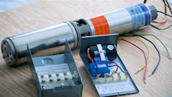
A 3-wire system (actually there is a fourth equipment ground conductor that is not counted in the number of wires) implies there is a control box inside the house, containing a large electrolytic capacitor, microprocessor, and other electronics (Photo 1). In contrast, a 2-wire system omits the in-house controller so that the capacitor is inside the hermetically sealed underwater motor. Although this arrangement makes for a cheaper initial installation, when it comes to repair, options are limited.
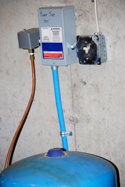
To efficiently diagnose one of these systems, it's necessary to clearly understand the wiring arrangement you're dealing with — at least external to the control box and motor. A 240V branch circuit from a double-pole breaker within the entrance panel is run to an off-the-shelf double-pole pressure switch, which is actuated by low cut-in and high cut-out water pressure inside the pressure tank. This switched power goes to the input terminals of the control box.
The control box output exits the building, is buried in the same trench with the water pipe, and emerges from the ground in metal or PVC raceway where it enters the well cap through a passage designed for the purpose. Inside the well cap, it's usually spliced with twist-on wire connectors, and then goes down along the water pipe to the pump motor, which comes furnished with a pigtailed set of three wires (plus equipment ground). These are connected to the pump cable by means of crimp-on connectors and heat-shrink tubing, which is the same as an underground splice kit. The spliced wires should be routed inside the torque arrester — an expandable rubber cylinder that keeps the pump/motor assembly centered and minimizes counter rotational motion and wire chafing.
The pump cable, which comes from the control box output terminals, consists of red, yellow, and black (plus green) twisted conductors. Because they are not jacketed, you must run the indoor segment in raceway. As for the outdoor portion, you can direct bury it, as far as the NEC is concerned. However, state and local well installation regulations may call for UL-listed gray RNMC or similar protection to the wellhead.
Many people assume that the well cable is made up of two hot legs with a neutral; however, that is not the case. The red is start, the black is run, and the yellow is common. One of the functions of the control box is to energize the red for a short period of time so that the pump motor can get up to speed, after which black is switched online.
One large manufacturer offers the motor and control box, which are used by many pump manufacturers. The pumps are bolted onto the motors (with matching splined shaft). However, one major manufacturer makes its own motor and control box, which are not interchangeable. As for the others, motors and control boxes may be interchanged as long as horsepower, phase, and voltage are a match.
The great advantage in the universal control box is that the cover contains the electronic components so you can replace them without doing any rewiring.
Stepping through a diagnosis
In troubleshooting a nonfunctioning submersible pump system, you must strive to diagnose and repair the problem without unnecessarily pulling the pump out of the well or digging up the buried line.
Let's say a homeowner has a drilled well with a submersible pump located 500 feet from the house set at a depth of 300 feet. The complaint is that when a faucet is turned on, there is no water. The homeowner says the system has been in place for several years, and there has never been a problem. Because it has rained a lot all summer, lack of water in the well can be ruled out. There is a good probability the pump has failed due to sand preventing the impeller from turning or because the motor has seized up. But because pulling a pump that is set at 300 feet is a fairly difficult task, other possibilities are pursued first.
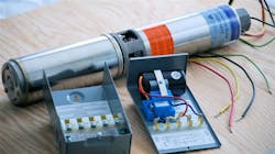
It is a 3-wire system, and all electronics are mounted inside the control box cover. After verifying with a voltmeter that there is power to the input terminals — indicating house wiring and pressure switch are functional — a new cover of the correct horsepower rating is acquired. The cover contains a capacitor, relay, microchips, and other electronic components (Photo 2 on page C26). When it's snapped in place, it supplies power to the pump motor via 3-wire (plus equipment ground) underground pump cable. Unfortunately, this procedure did not cause water to flow to the pressure tank, so other avenues must be pursued.
At this point, it's time for the “divide-and-conquer” troubleshooting technique. The idea is that when a system consists of a number of components connected serially — and the endpoint is not receiving power — the most efficient strategy is to perform a test at the midpoint to narrow the focus, not necessarily spatially but in terms of probable causes. The bad half can be tested in turn at its midpoint, allowing the technician to methodically zero in on the problem location. This technique is especially useful when working on large complex machinery or wiring systems.
In the case of the pump system, it is decided to take measurements at the wellhead. The well cap is removed. The three wires at that point are frequently spliced with twist-on wire connectors, which can be removed to access test points. If not, the conductors can be cut with power locked out and later reconnected using silicone-filled twist-on wire connectors. Although it's found that voltage is present, a clamp-on ammeter reveals no current flow with the wires reconnected. Thus, an underground line fault is eliminated. Before pulling the pump, go back to the control box and take additional resistance and current measurements, referring to the information printed inside the control box.
With a good helper and power locked out, you can pull a pump-motor assembly in about an hour. Now is a good time to visually check the cable for abrasion or other damage. Separate the motor from the cable, and do meter tests to the cable to further isolate the problem. Let's assume the cable turns out to be in good condition. If the earlier clamp-on ammeter test had indicated excessive current flow — and there is no line damage — it looks like the motor has one or more shorted windings, is seized, or the pump will not turn. Before giving up completely on the motor, consider the possibility that the motor pigtail has acquired a short circuit, possibly due to lightning damage. This wiring harness has a plug-in connector right on the motor and can be unplugged after removing the protective metal channel. If that is not the problem, unbolt the pump from the motor, and see if the motor shaft will turn by hand. If it is seized, you must replace the motor. This is because it's a sealed unit; therefore, it's not possible to rebuild it. If it will turn, then you can conduct a brief dynamic test.
Another piece of advice is to make sure you have a good equipment ground connected. You should clamp the motor to a large, dry piece of plywood. Do not touch the metal case while the motor is energized. Fire it up very briefly, because it is designed to be run submerged in water for cooling purposes.
If the motor runs, there is the possibility that the pump has become sand bound. It is a simple matter to take it apart and clean it, reassemble the unit, and retest. You can inspect the pump impellers and replace them if worn or damaged. If it runs and meter readings are good, reset the pump a few feet higher so the problem does not recur.
Usually, the foregoing procedures will result in a successful repair. If not, you'll have to retrace your steps, and see if you made a false assumption or misread data somewhere along the line. It's also possible there is partial damage to the cable that did not show up during your visual inspection. This can be misleading and cause you to go around in circles. Another curve ball that may be thrown your way is when there are two or more faults. Finding and correcting one of them will not restore normal operation. The answer to both of these problems involves using patience, persistence, and perception. You have to go over the whole system, keep isolating stages, and apply logic to each one.
Beyond the basics
One mistake many beginning electricians make is they think they're going to find the problem in 5 minutes. If the above described procedure doesn't pinpoint the problem, then you'll need to turn to other troubleshooting techniques.
Suppose the readings at the well cap indicate there was no fault in the cable going down inside the well casing, and the pump motor was good. Ohm readings from the wellhead back to the control box — with wires disconnected at the wellhead and control box cover removed — indicate a short between yellow and black conductors. Then you know the fault is in the underground portion of the circuit, which is buried at a depth of 4 feet, for example. At this point, you know some digging is required.
Because backhoe time is costly, careful planning is essential. What is the minimum digging required to locate the fault? Can cutting the wire to take readings at various points along the cable be avoided? If you use the divide-and-conquer method again, it's possible to dig at the midpoint of the underground portion of the line and take readings to ascertain which half of it contains the fault. Then repeat this process by digging at the midpoint of the faulty half of the line — further narrowing down the problem segment. This limits the amount of digging you'll have to do to locate the exact point of failure. As for cutting the wire to take measurements, that is not necessary. Apply a voltage in series with a heavy load and use a clamp-on ammeter to perform the test.
You might also consider what some view as an even better method — one that involves a more sophisticated test and less digging. Take ohm readings from both ends to locate the short. If the reading at the house is double the reading at the wellhead, then you know the short is one-third the distance, or about 166 feet, from the well.
Herres is a licensed master electrician in Stewartstown, N.H. He can be reached at [email protected].
About the Author
David Herres
Licensed Master Electrician
David Herres is a licensed master electrician in Stewartstown, N.H. He can be reached at [email protected].


