When a manufacturer of plastic bag and packaging materials set out to expand its operation, it leased additional space in a large industrial building that already housed its offices and production operations. But before moving in, some new equipment would be necessary. To make this happen, an electrical contractor was promptly hired, and the facility was shut down for one day while the contractor connected the new equipment to the production line and performed final installation details on the electrical system.
Upon accepting the job, the electrical contractor most likely did not anticipate any problems with the routine installation, let alone a serious accident that would end in an arc blast, an injured worker, and excessive damage to the facility's electrical equipment. After the accident, Anderson Engineering received a call from the electrical contractor's liability insurance carrier to help determine the cause of the accident.
Before determining the cause, it was important to recreate the circumstances leading up to the incident. Therefore, we gathered the following details as background on the scene.
Setting the Stage
The local power utility supplied 480/277V 3-phase electrical service to the facility through a 1,500kVA, pad-mount transformer located on the north side of the building. The service entrance conductors fed into a 3,000A, 480/277V, 3-phase disconnect. In this case, the disconnect was a manually operated, spring-loaded bolted contact switch with quick-positive switching action. A nameplate date code showed it was manufactured in 1969.
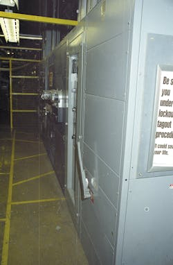
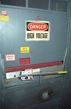
The switch was located in the main switchgear area along the interior north wall, as shown in Photo 1. Feeder conductors traveled from the switch output buses to various disconnects and subpanels located in the main switchgear area. The production equipment motors and conveyor drives used in the factory were then fed from these subpanels.
To perform their work safely, the electrical contractor de-energized the entire facility by switching off the 3,000A bolted contact switch. After working through the night, the contractor was ready to re-energize the facility, start up the production machinery, and begin any necessary troubleshooting early the next morning. After re-checking the electrical connections, the crew attempted to engage the switch (see Sidebar: Inside the Switch, below). Unfortunately, the workers discovered that it would not move completely to the ON position.
The Accident
In this case, there was apparently a mechanical problem within the switch. While it would close electrically, the switch plates would not move to the fully ON position. The electricians tried to fully engage the switch numerous times with no luck. They knew that if the movable and stationary contact plates did not make full contact, the large operating current could result in damaging resistive heating at the contacts.
Troubleshooting the situation, one electrician decided to use a long flat-headed screwdriver as leverage to try and force the switch fully closed. After wedging the tip of the screwdriver between the dead-front panel and the switch arm, he pulled down on the screwdriver handle, using it as a lever to achieve the force necessary to close the switch. As he pressed down on the handle, the tip of the screwdriver slipped through a gap between the switch and the dead-front panel, making contact with a bolt on one of the upper left phase buses inside the panel while the shaft was touching the grounded portion of the switch arm assembly.
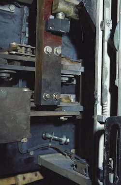
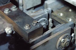
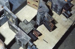
This act initiated a direct phase-to-ground short (see Photos 2A, 2B, 2C), resulting in an intense arc blast. Fortunately for the electrician, the main force of the blast shunted downward and was partially blocked by the dead-front panel. Because he was holding onto the insulated screwdriver handle, he was not shocked. However, he was shaken and temporarily blinded for a few hours by the flash of light generated in the arcing event.
The Aftermath
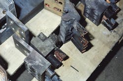
Electrically, the arc blast created severe problems for the packaging facility. Molten metal ejected from the arcing event damaged the feeder connections and conductors at the output of the switch. This apparently created a secondary phase-to-phase arcing event between the left and center phases (Photo 3). This arcing event apparently caused an overload on the utility transformer, resulting in one of the phases shorting out. The facility was left without power until the electric utility could replace the transformer.
The building owner hired a different electrical contractor to replace the damaged switchgear and feeder conductors. This new contractor replaced the feeder conductors and connections. Its employees also allegedly cleaned the switch and put it back into service. Along with the replaced transformer, the electrical system operated properly for the next few days. However, the switch began tripping about a week later, so workers at the plant braced the switch arm closed with a piece of 2x4 lumber.
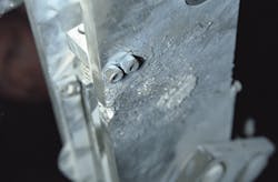
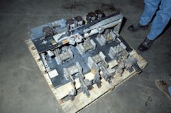
Finally, a third electrical contractor was hired to replace the switch entirely. This contractor took possession of the damaged switch (Photo 4) and the original damaged feeder connections. Anderson Engineering was then able to examine the damaged switch and conductors at its facility, where we discovered the aforementioned arcing event damage.
Investigation and Analysis
The ensuing inspection showed the switch arm was actually broken. Although it's unknown how this occurred, we believe this possibly happened when the switch attempted to trip while being held closed — or it may have been stressed from multiple actuation attempts.
Although the switchgear was damaged by the arcing event, the switch was most likely suffering from a mechanical failure when the original electrical contractor attempted to close it. In this case, the switch may not have been maintained properly. Manufacturers typically require a regular cleaning and maintenance schedule to keep their equipment operating properly. This could include replacing or polishing the contact plates, as well as lubricating the switch mechanism and the plates themselves. This switch should also be actuated on a regular basis and checked for signs of abnormal resistive heating, among other necessary performance tests.
The arcing event caused further problems as well. Although the switch appeared to sustain little physical damage, it should not have been put back into service. If the bolted switch plate connections are not tight (and do not have low resistance throughout), hot spots can develop at the higher resistance areas. High-resistance heating can melt the switch plates, permanently damaging the switch, and possibly even weld the contact plates together, preventing the switch from opening if a downstream fault occurs.
Not much is known about the safety measures taken by the original electrical contractor during the installation of the new equipment. However, the contractor should have been following the rules laid out in the NEC, as well as NFPA 70E: Standard for Electrical Safety in the Workplace.
The employees were actuating a switch with the panelboard cover closed, and were not working on exposed, energized conductors. Based on that fact, some may conclude that NFPA 70E arc-flash PPE requirements don't apply, However, even a dead-front panel will not block severe arc blasts. In a situation such as this, when working on equipment in an unknown condition, it's best to be as safe as possible. Openings or vents in a panel increase the possibility of an arc blast escaping the panel, and the level of personal protective equipment (PPE) may need to be increased beyond the recommended level.
Looking at the 2004 edition of NFPA 70E, in lieu of flash hazard analysis, Table 130.7(C)(9)(a) should be used to determine the appropriate PPE. According to the table, the workers were operating an energized 600V fused switch with the enclosure doors closed, which is a Hazard/Risk Category 0 operation. According to Table 130.7(C)(10), Hazard Category 0 protective clothing and PPE include a non-melting, natural-fiber long-sleeve shirt and pants, as well as safety glasses.
Going beyond simply operating a switch and attempting to use a screwdriver to force it closed is not accepted by OSHA workplace safety standards and violates NFPA 70E Art. 130.6(E)(1) — improper use of a conductive tool.
When the switch wouldn't close properly, the electricians should have stopped their work and taken time to resolve the issue. The safest option is to work on completely de-energized equipment. Therefore, they should have coordinated with the electric utility to shut off electrical service at the transformer.
If they decided not to shut off utility power, the upstream side of the switch would still be live, even when the switch is off. With the panelboard cover open, they would be exposed to energized conductors at the upstream switch lugs. As a result, they would have had to take increased safety precautions and follow the provisions of Art. 130, by using Table 130.7(C)(9)(a) or conducting an arc-flash hazard analysis to determine the appropriate protection boundaries and suitable PPE.
The second electrical contractor sent to work on the facility created further safety hazards when it put the original switch back into operation without repairing the initial arcing damage. At the very least, the switch should have been rebuilt and all damaged parts replaced. Then, all aspects of the rebuilt assembly should have been tested, including the proper functioning of the ground fault trip mechanism.
The cause of the subsequent switch tripping is unknown. The switching mechanism was possibly damaged during the arc fault. Another possibility is a high-resistance ground fault path may have been formed between phase and ground through the debris and soot created in the arcing event. This could cause the ground fault detector to trip.
The third contractor completely replaced the switch. However, at the time of our scene visit, they had not yet replaced the original dead-front panel with one that properly fit the new switch (Photo 5). Instead, they temporarily covered the openings with a thin layer of cardboard and tape. Although the switchgear area appeared to be cordoned off into a controlled access area, they could have blocked the panelboard opening with sheet metal or a non-combustible, insulating material.
Fortunately, the electrician in this case recovered from his injuries, and a worker's compensation claim against his employer was settled. Further legal issues are unknown, although there may have been a claim against the contractors for negligence in damaging the switchgear and a lost revenue/productivity claim when the packaging facility was left idle for an extended period of time.
Paris is a forensic electrical engineer with Anderson Engineering, New Prague, Minn. He can be reached at [email protected].
Sidebar: Inside the Switch
As a point of reference, a bolted contact switch is made up of three bolted plate connections — one for each phase. A switch of this amperage also requires a low-resistance connection between the stationary and movable contact plates. When the switch is actuated, it engages a bolting mechanism that applies constant pressure to hold the contacts closed and tight, which creates a great deal of friction. The switch arms are connected together so they will engage simultaneously when the main switch bar is moved to the ON position.
Because the switch also needs to open at a moment's notice, the main switch arm is “spring-loaded.” This arrangement assists with quickly breaking the circuit when the switch opens. The switch arm requires a number of actuations in order to “charge” the spring-like mechanism; these actuations also help ratchet the switch to a tightly closed position. The spring mechanism stays charged so the switch will be able to open quickly, either manually or when tripped by an external fault detection device. The subject switch was equipped with a ground fault detector, but other sensors could trip the switch via a fuse melting open, phase loss, zero-sequence fault, etc. The detection device emits a voltage signal that will open a solenoid holding back the spring mechanism. The spring mechanism will then engage and open the switch. In the case of the subject bolted-contact switch, the switch arm would then physically move 90 degrees to the OFF position.
