Article 501 provides the requirements for Class I locations, such as the refinery shown in Photo 1. In the May issue, we described the Division system outlined in the NEC, which further breaks down the class. If the ignitable material is normally present (in sufficient quantities to present a hazard), then it’s a Div. 1 location. Less stringent requirements apply for a Div. 2 location, because ignitables are present only in abnormal circumstances.
Article 501 gives you the option of using the Zone system (Art. 505) instead of the Division system [501.2]. Articles 502 and 503 also give you this option, but inconsistent with Art. 501 they do it in Subsection 6 [502.6, 503.6]. We’ll discuss Art. 505 requirements in a future installment.

Article 501 presents most of its requirements with a pattern of “Div. 1 in subsection A” and “Div. 2 in subsection B.” This first example occurs in Part II. There, we can see that 501.10(A) provides the wiring requirements for Div. 1, while 501.10(B) provides the wiring requirements for Div. 2. This pattern repeats many times, though it’s not a hard and fast rule.
Wiring methods
If a wiring method is allowed for Div. 1, it’s also allowed for Div. 2 [501.10(B)(1)(1)]. There are four general differences in wiring method requirements for Div. 1 versus Div. 2:
1) Fittings and flexible cords used in Class I, Div. 1 areas must be listed for Class I, Div. 1.
2) You must run conductors in RMC or threaded steel IMC raceways in Div. 1 (there’s an exception for concrete-encased PVC), but you can use any gasketed enclosed busways or wireways for Div. 2.
3) More cable types are allowed for Div. 2.
4) In Div. 2, you can install nonicendive field wiring using any of the wiring methods permitted for unclassified locations.
Sealing requirements

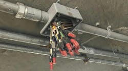
Nearly half of Art. 501 is devoted to presenting sealing requirements, a fact that visually distinguishes it from Art. 502 and Art. 503 (see SIDEBAR: The Class Sealing). The purpose of the seals (Photo 2) is to “minimize the passage of gases and vapors and prevent the passage of flames from one portion of the electrical installation to another through the conduit.” [501.15 Informational Note 1].
You must install seals:
• At each conduit entry into an explosionproof enclosure if it contains apparatus considered to be an ignition source during normal operation, or if the entry is trade size 2 (or larger) [501.15(A)(1)]. This also applies to Div. 2 [501.15(B)(1). Some exceptions exist; for example, if the apparatus are within a hermetically sealed chamber.
• In each conduit entry into a pressurized enclosure, if the conduit is not also pressurized [501.15(A)(2)]. Does not apply to Div. 2.
• In each nipple or conduit run connecting explosionproof enclosures [501.15(A)(3)].
• In each conduit leaving the Class I, Div. 1 location [501.15(A)(4)] to any area; in each conduit leaving the Class I, Div. 2 location to an unclassified area [501.15(B)(2)].
The seals themselves must be explosionproof, except:
• Between a Class I, Div. 2 location and an unclassified area.
• Where not required in intrinsically safe systems [504.70].
To be considered explosionproof, the seals must meet the following requirements [501.15(C)]:
• Enclosures must have an integral means for sealing or for using sealing fittings listed for the location.
•The sealing compound must seal against vapors, be impervious to the environment of use, and have a melting point of at least 200°F.
• The sealing compound must be at least as thick as the trade size of the sealing fitting.
• You can’t put splices or taps in sealing fittings, nor can you put sealing compound in fittings that contain splices or taps.
• Multi-compartment assemblies must be identified for the location, if certain conditions exist.
• Conductor fill is 25%, not 40% (unless specifically identified for higher fill).
Cables must be sealed at all terminations [501.15(D), [501.15(E)]. If a cable is capable of transmitting gases or vapors through the cable core:
• For Div. 1, seal it in the Div. 1 location after removing the jacket and any other coverings. The sealant must surround each conductor and the insulated jacket [501.15(D)(2)].
• For Div. 2, no additional sealing is required unless the cable is attached to process equipment (or devices) that may cause a pressure of 1,500 pascals in a cable end. In that case, install a seal or barrier that will prevent flammables from migrating to unclassified areas [501.15(E)(3)].
Liquid
A concern with any type of sealed raceway/enclosure system is that moisture will accumulate inside it. Where such an outcome is probable, you can install an approved means for draining the condensation. If such condensation is probable in a motor or generator, you must arrange the conduit system in a way that minimizes the entrance of liquid [501.15(F)].
If liquid in these systems might come in contact with conductors, specify an insulation type suitable for wet conditions or protect the conductors with an approved means, such as a lead sheath [501.20].
Process sealing
The 2011 edition of the NEC added process sealing requirements [501.17]. A process seal prevents process fluids from migrating into the electrical system. If process-connected electrical equipment incorporates only a single process seal, you must provide an additional barrier (in case the seal fails). If the equipment does not rely on a single seal, then you don’t need to do anything extra.
Spark prevention
Most of the emphasis in Art. 501 is on containing the flame, but Art. 501 also provides requirements to prevent ignition. The first is “no uninsulated exposed parts operating at over 30V” (15V for wet locations) [501.25].
Subsection 501.25 says that all Class I wiring and equipment must be “grounded as specified in Art. 250.” But Art. 250 does not require load side equipment to be grounded (connected to earth), and such a connection serves no electrical purpose. So what gives?
A quick visit to Art. 100 clears up the confusion. What you want to do is bond (not ground) all of the equipment, thus eliminating differences of potential that could provide an ignition source (Art. 250, Part V). You also want to ensure the integrity of the grounded conductor (typically the neutral). It’s also critical that you don’t substitute grounding for bonding and thus create an unsafe system.
Class I locations must also have surge protection at the enclosures. Surge-protective capacitors must be of a type designed for specific duty [501.35].
You can’t use multiwire branch circuits in a Class I location [501.40] unless the circuit disconnect opens all ungrounded conductors simultaneously. Incidentally, this is also true for Class II locations [502.40].
Equipment
A transformer vault must not have a door to the Div. 1 location; for Div. 2 locations, the rule is waived if the vault is identified as a Class I vault [501.100].
If the transformer contains a liquid that will burn and the vault is in a
Div. 1 location:
• Provide ample ventilation for the continuous removal of flammable gases or vapors.
• Ensure vents and ducts lead to a safe location outdoors.
• Ensure vents and ducts are big enough to relieve explosion pressure within the vault, and all indoor vent ducts are of reinforced concrete construction.
Provide all instrumentation with purged and pressurized enclosures identified for Class I locations and identified for Div. 1 or Div. 2 as appropriate. In some circumstances, you can use general enclosures for Div. 2 [501.105(B)(3) and (4)].
Provide electrical controls (e.g., switches, breakers), control transformers, and resistors with enclosures identified for use in Class I locations. In a Div. 2 location, you can use a general enclosure under certain conditions [501.115, 501.120].
Motors and generators must be identified for use in Class I, Div. 1 (or Div. 2 for a Div. 2 location). Two special types of enclosed motors are exempted from this requirement.
Luminaires used in Class I, Div. 1 must be identified and marked for that use. For Div. 2, the same applies unless their surface temperature won’t exceed 80% of the ignition temperature of the gas involved [501.130].
911 for 501
Art. 501 is the most stringent of the 501-2-3 trio. Its requirements can be a bit overwhelming if you try to take them in all at once. You can reduce the stress by remembering that it actually provides two sets of requirements. If you keep Art. 501’s A/B format in mind, you often don’t need to read a given subsection in its entirety. You can read either the A or B, depending on whether you have a Div. 1 or 2, respectively.
Lamendola is an electrical consultant located in Merriam, Kan. He can be reached at [email protected].
SIDEBAR: The Class Sealing
Sealing requirements for Class I areas are understandably more stringent than those of Class II (Art. 502) areas, because it’s much more difficult to seal against gases than against dust. These requirements are the key difference between Class I and Class II installation work. Class III (Art 503) areas don’t require seals, because the wiring methods suitable for Class III locations provide a sufficient barrier against flying fibers.