Article 501 through 503 form a trilogy. Art. 505 provides an alternative to Art. 501; Art. 506 provides an alternative to Art. 502 and 503. Between these two sets is Art. 504. It’s sandwiched there because it applies to both sets. You can use intrinsically safe (IS) systems in all three classes of hazardous location, whether you use the division system or the zone system.
When installing IS systems, you can use any of the wiring methods suitable for unclassified locations [504.20]. This is an advantage that could save considerable money. So why not use 100% IS circuits and equipment rather than bother with those other Articles?

The answer to that question lies in the definition of “intrinsically safe.” The NEC doesn’t define this per se, but it does define four variations (IS apparatus, circuits, and system; plus different IS circuits). If we look at the definition of “IS circuit,” we see it’s a circuit that isn’t capable of causing ignition under specific conditions.
Those conditions are described in ANSI/UL 913-1997, “Intrinsically Safe Apparatus and Associated Apparatus for Use in Class I, II and III, Div. 1, Hazardous (Classified) Locations.” The requirements outlined in this standard are rigorous. Also, there are several levels of IS. Equipment with an IS label for one application might not be permitted for another.
IS has cost and complexity, so it isn’t a shortcut to eliminating the cost and complexity of applying the other relevant hazardous location articles found in the NEC — and you’re never going to make a large coal-handling motor IS. The motivation for using IS equipment has more to do with considerations of practicality, especially for operations and maintenance.
The IS labels apply to a wide range of items and equipment, including portables. For example, maintenance techs commonly carry radios. Those working in hazardous locations carry IS versions (labeled for use in that specific Class). The same thing applies to laptops, test equipment, electrical tools, and mechanical tools. An example of a mechanical tool is the brass hammer; it doesn’t spark upon impact. While Art. 504 doesn’t address portable equipment, using such items is part of working in hazardous locations.
Intrinsic safety is a system concept. We get a hint of this by reading the definitions in Art. 504. This fact becomes clear where the NEC requires you to install the equipment per the control drawing(s) [504.4]. The control drawing is the master plan for everything in an IS system. The Instrument Society of America (ISA) has a standard that addresses this drawing: ISA-RP12.2.02-1996.
Location
Suppose you have IS equipment in a Class II location. There’s a system configuration change, and now this location is Class I. Is that equipment, which carries an IS label, OK to leave where it is? Yes, but only if it’s identified for Class I [504.10(B)]. Otherwise, you’ll have to replace it with equipment that is.
You can install associated apparatus in any location for which it has been identified. If it’s not identified for the location, you can still install it there, if you protect it by other means identified in Arts. 501, 502, 503, and 505.
If installing “simple apparatus” (see definition in 504.2), you must calculate the temperature class following the instructions in 504.10(B) and using Table 504.10(B).

Wiring methods
You can install IS apparatus using any of the wiring methods suitable for unclassified locations. You can also use those covered by Chapters 7 and 8, but you must provide sealing (which we’ll cover in a moment) and separation (which we’ll cover next) [504.20].
Four degrees of separation
You must separate IS conductors of one circuit from IS conductors of another circuit by at least a quarter inch [504.30(B)] (unless the control drawing permits tighter spacing). You can achieve separation by running each circuit in a grounded shield or by ensuring each conductor has insulation at least 0.01 in. thick.
You must separate IS conductors from those that aren’t IS, and the rules depend upon which of three scenarios you have:
1) In raceways, cable trays, or cables. You can’t run IS conductors in any raceway, cable tray, or cable with non-IS conductors. One of the four exceptions to this rule might apply to your installation [504.30(A)(1)].
2) Within enclosures. You must secure the IS conductors so if a conductor might come loose from a terminal, it will be unlikely to come into contact with the terminal. You also must separate the two types of conductors by one of the four methods listed in 504.30(A)(2)(1)-(4).

3) Other (not in raceway or cable systems). Provide at least 2 in. of separation, and secure the IS conductors to avoid contact with non-IS conductors.
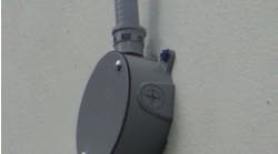
Applying the raceway, cable tray, and cable rules is pretty straightforward; just run IS conductors in their own raceway, cable tray, or cable. But what happens when these get to an enclosure? How do you keep them separated? How do you secure them to prevent contact? You can see solutions to these and other problems in the Photos. In addition to correctly using application-specific panel systems and isolators, the installers executed superior workmanship.
Grounding and bonding
The reason for installing IS equipment would be defeated if enough potential (voltage) built up between it and other equipment. Thus, IS equipment must be connected to the equipment grounding conductor (EGC) [504.50(A)]. This is really a bonding system, not a grounding system. Driving a ground rod and connecting to that will not eliminate dangerous differences of potential.
You must also “ground” the associated apparatus and cable shields per the control drawing [504.50(B)]. Typically, this means connecting only the termination panel end of the cable to this bonding system. Especially with low-voltage sensors, such as thermocouples, if you also connect the field end, you may create a ground loop that circulates enough current to overwhelm the actual signal. If the operator display shows an ambient temperature of 200°F outside, you probably have a ground loop on the thermocouple shielding.
The NEC also provides instructions on what to do where it’s required that you connect to a ground rod [504.50(C)]. Before making that connection, question the requirement. What will it accomplish, and what kind of path is it providing for undesired current? Draw out the circuit, and you’ll be able to see the answers. Connecting load side equipment to a ground rod generally won’t accomplish anything except waste a ground rod. Make sure you bond to eliminate differences of potential; grounding will not achieve this.
Bond IS apparatus per 250.100 [504.60(A)]. In unclassified areas where metal raceways contain wiring for IS systems, bond those raceways per 501.30(A), 502.30(A), 503.30(A), or 506.25 as applicable.

Sealing
The exception to 504.70 says you don’t need seals on enclosures that contain only IS apparatus, except as required by 501.15(F)(3). The odd thing here is there’s no 501.15(F)(3) in the 2011 NEC. It does, however, exist in the 2008 NEC.
This exception should say, “…except as required by 501.17.” That’s where 501.15(F)(3) was moved to. It’s been completely rewritten and is more detailed than in the 2008 NEC.
As with any complex document, these kinds of oversights do sometimes happen with the NEC. So it’s always good to learn the Code changes with each revision, and keep your previous copy of the NEC handy.
Labels
Efficiency, maintainability, and accuracy are among the many good reasons for an electrical contractor or a maintenance department to have a high-quality label-making system for cables and terminations. Those who install or maintain IS systems have an additional reason: compliance. Trying to comply with the label requirements for IS circuits with a permanent marker and tape is an exercise in futility. Consider just two of the several labeling requirements. You must:
1) Mark all terminals in a way that’s intended to prevent unintentional interference with the circuits during testing and servicing [504.80(A)]. This almost certainly excludes anything you can do by hand.
2) Identify all raceways and other wiring methods (for IS systems) with permanently affixed labels that bear the words “Intrinsic Safety Wiring.” If you need to do a few hundred labels by hand, it’s going to take much time and probably a few choice words along the way. With an industrial labeler, you not only reduce errors, but also dramatically save time.
Getting it intrinsically right
Begin with a careful review of the control drawing. Then select the correct equipment. Remember, a system gets its IS label when it’s deemed incapable of causing ignition in a given environment. Make sure every bit of IS equipment going into a given location has that location identified on its IS label.
This designation assumes ignition ability won’t be added by the choices made during the installation. Pay special attention to equipment bonding and the use of barriers, as these are two areas where installers can easily go astray. Finally, using a specialized IS panel system reduces installation time and provides strong visual cues for error prevention.
Lamendola is an electrical consultant located in Merriam, Kan. He can be reached at [email protected].