The Impact of 2014 NEC Changes on Data Center Design
Data centers are unique facilities with electrical systems designed to achieve high availability and energy efficiency. If not properly designed, these robust systems can result in undesirable complexity and increased safety hazards. Several Articles in the NEC deal directly with mission-critical data centers, including Art. 645 (Information Technology Equipment), Art. 646 (Modular Data Centers), and Art. 708 (Critical Operations Power Systems). Let’s take a look at some of the 2014 NEC changes that will have the greatest impact on data center design:
1) The revised definition of “selective coordination” will pose new challenges for critical operations data systems and may require specific selection of equipment as well as larger, more expensive overcurrent protective devices.
2) All circuit breakers rated 1,200A and above are required to have an approved method for reducing clearing time, regardless of whether an instantaneous trip function is present or not. The change is meant to further reduce arc energy, but will also increase equipment costs and complexity within the data center.
3) Electrical rooms that contain equipment rated 800A and above must have outward swinging egress doors and listed panic hardware. The reduction from 1,200A will encompass more electrical rooms and further protect worker safety.
4) The most significant change in Art. 645 is the elimination of smoke detection below the raised access floor. The NEC now permits the critical cooling serving the ITE to remain functional during an underfloor smoke event.
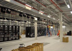
5) The new Art. 646 Modular Data Centers (MDCs) validates the increasing popularity and industry acceptance of MDCs (Photo 1). While many of the same rules can be found in other sections of the NEC, the information is now consolidated, providing users with a single reference point as well as a forum for future expansion. Article 646 will continue to evolve in the upcoming Code cycles as the MDC industry further develops.
In addition, there are several other widespread Code changes that affect data center design, such as:
• Expansion of DC systems and wiring requirements.
• New requirements for markings and labels.
• Increase in the AC and DC voltage threshold from 600V to 1,000V to match standards in other parts of the world, such as the IEC and BS series of standards.
• Use of the term “switchgear.”
The NEC definition of switchgear, previously referred to as metal-enclosed power switchgear, was revised in Art. 100 to be more comprehensive. It is now a generic term that encompasses many different types of metal-enclosed switchgear, including 1,000V and above. Switchgear was added to the title of Art. 408 and many other sections where the term switchboard was previously used.
The terms switchgear and switchboard are often interchanged without recognizing the fundamental differences. For example, low-voltage metal-enclosed switchgear is constructed to standard UL 1558 and is compartmentalized with physical barriers between circuit breakers and bussing. Enclosure depth is typically greater than switchboard construction, and switchgear requires front and rear access. Switchgear can be designed with 30-cycle interrupting ratings and can also be designed to be arc-resistant.
Switchboards, on the other hand, are constructed to standard UL 891 and are not typically compartmentalized, 30-cycle rated or available in an arc-resistant construction. Switchboards can be designed front accessible only. Circuit breakers can be group or individually mounted.
Article 110: Requirements for Electrical Installations
Service equipment is required to be field-marked with the maximum available fault current and the date that the calculation was performed. The available fault current is often calculated using the infinite bus method, which assumes there is zero impedance in the upstream electric utility system. This calculation method results in the highest value of fault current, which is an acceptable practice for verifying equipment withstand and interrupting ratings. However, during modeling, this theoretical value can result in overcurrent devices operating more quickly than they would in reality. This could result in dangerously low arc flash incident energy levels being calculated and improper selection of personal protective equipment (PPE). The new Informational Note in Sec. 110.24 advises that these markings should not be used for determining arc flash incident energy levels, and guides users to NFPA 70E, Standard for Electrical Safety in the Workplace.
Personnel doors from working spaces containing equipment rated 800A or above (reduced from 1,200A) must have outward swinging door(s) equipped with listed panic hardware in accordance with 110.26(C)(3). The intent is to maintain and protect a safe egress path during an emergency situation, during which an injured worker may not have full use of their hands or eyes.
Many data centers have outdoor equipment yards that contain transformers, generators, switchgear, and mechanical equipment. This outdoor equipment is now subject to the same dedicated equipment space requirements as indoor equipment based on 110.26(E)(2)(b). Outdoor equipment yards and similar areas must be carefully coordinated between all trades to ensure dedicated equipment spaces are free of mechanical, plumbing, fuel, piping, and other foreign systems.
Article 240: Overcurrent Protection
The two main factors that affect arc flash incident energy are current and time. The longer a fault exists, the higher the resultant arc flash severity. Unlike short circuit current — where the device closest to the source has the highest value — a higher arc flash category may exist at locations further from the source due to the time it takes for the overcurrent device to operate because the fault current is lower. Unfortunately, maximum selectivity and maximum service continuity can be in direct conflict with one another. Ideally, any overcurrent protective device that detects a fault should open instantaneously to reduce arc energy. However, at the same time, selectivity is often necessary to ensure that upstream devices are restrained long enough for the device nearest to the fault to open first to minimize the impact of the fault on the remainder of the system.
A significant change to the 2014 NEC relates to Sec. 240.87 [Arc Energy Reduction], which now requires that all circuit breakers rated 1,200A and above, with or without an instantaneous trip function, be provided with an approved method for reducing clearing time during a fault. The following methods are indicated for reducing clearing time: zone-selective interlocking, differential relaying, energy-reducing maintenance switching with local status indicator, energy-reducing active arc flash mitigation system (e.g. high-speed shorting switches, optical sensors, etc.), and approved equivalent means.
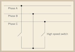
High-speed shorting switches are most commonly applied to medium-voltage systems. When an arcing fault is detected, these devices actively close a switch to create an intentional 3-phase fault (Fig. 1), which increases the fault current and trips the associated protective relays faster. Optical relaying is an alternative method for consideration, where deemed an “approved equivalent means” by the local AHJ. These systems detect an arcing fault by looking for specific light and current characteristics and trip only when both are present. Project engineers must weigh the various pros and cons for each method and determine the most appropriate strategy on a case-by-case basis.
Article 250: Grounding and Bonding
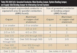
Table 250.102(C)(1) was added for the sizing of grounded conductors, main bonding jumpers, system bonding jumpers, and supply-side bonding jumpers (Table). Previously, Table 250.66 was used for sizing these fault current-carrying conductors, which was unclear because of the title: “Grounding Electrode Conductors.” The change is relatively minor because the two tables contain similar requirements.
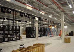
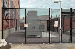
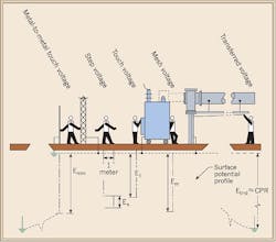
Many data centers are supplied by outdoor electrical substations that are often enclosed by metallic fences to restrict access to qualified personnel (Photo 2). Based on the new provisions in Sec. 250.194, metal fences and other metallic structures must be grounded and bonded to limit the rise of hazardous step, touch, and transfer voltages (Fig. 2). IEEE 80 Guide for Safety in AC Substation Grounding is the industry standard for fence grounding.
Article 310: Conductors for General Wiring
Conductors and cables installed on rooftops exposed to direct sunlight are subjected to higher ambient temperatures than the surrounding environment. These conditions require the ampacity of the conductors to be temperature-adjusted, which typically results in larger size conductors. An Exception added to Sec. 310.15(3)(c) allows Type XHHW-2 conductors to be used without temperature adjustment. Type XHHW-2 conductors are comprised of a thermoset insulation suitable for high ambient temperatures, which may be simpler and more cost effective than increasing conductor and raceway sizes.
Article 445: Generators
The definition of “separately derived system” was revised in Art. 100, which now acknowledges that the two separate electrical sources may be connected through grounding and/or bonding. Generators may or may not be installed as separately derived systems depending on the specific application and this will affect the design of ground fault protection schemes and transfer equipment. Separately derived generators have the neutral or grounded terminal bonded to the generator frame, and use 3-wire distribution with no neutral or 4-pole transfer equipment to switch/isolate the two source neutrals. Non-separately derived systems do not have the neutral bonded to the generator frame, and use 4-wire distribution and 3-pole transfer equipment with unswitched neutrals. It is difficult to determine whether a generator is separately derived or not based on cursory observation alone. Therefore, the NEC added provisions in Sec. 445.11 that require generator manufacturers to provide a marking that indicates whether the neutral is bonded to the generator frame. The marking must be revised if the system is modified.
Article 480: Storage Batteries
UPS systems often use stationary storage battery systems to maintain power to critical IT equipment for the brief period of time when both electric utility and generator power sources are unavailable. There are different battery technologies on the market; the most commonly used in data centers are vented type (flooded wet cell) or sealed type (valve-regulated). Many batteries emit hydrogen gas during normal charging cycles — vented batteries more than sealed batteries. To coordinate with building and fire safety codes, Sec. 480.9 requires provisions “appropriate to the battery technology” be employed to prevent the accumulation of explosive or otherwise harmful gasses.
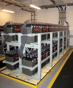
Battery installations must comply with 480.9(C), which references 110.27 for guarding of live parts. Minimum clearances are indicated. Additional clearances should be considered to enable access for rigging equipment used during future battery replacements (Photo 3). Battery rooms may also contain emergency showers, eye washes, and spill containment, all of which should not encroach on the dedicated equipment and working spaces.
Article 645: Information Technology Equipment
This Article covers equipment and installation requirements for information technology equipment (ITE) rooms. These rooms are power-intensive and cooling-sensitive environments — two aspects that present many unique safety challenges. Article 645 permits the use of alternate, less stringent wiring methods, provided that all six conditions listed in Sec. 645.4 are met.
Requirements and descriptions for HVAC systems in ITE rooms are clarified in 645.4 [Special Requirements].
Non-plenum rated power cables, communications cables, cord and plug connections, and receptacles are permitted to be installed below a raised access floor used as an air plenum, provided the provisions of Sec. 645.5(E) are followed. Previous editions of the Code required smoke detection under the raised floor to cease the circulation of air upon activation. The requirement for under floor smoke detection and to stop air circulation under the floor was removed from 645.5(E)(4). Smoke detection under the raised floor may be required by other building codes or standards, but is no longer required by the NEC.
Section 645.14 [System Grounding] was added to specifically indicate that separately derived grounding systems shall meet the requirements of Art. 250. In addition, Sec. 645.15 states that grounding and bonding shall comply with Art. 250.
Declaring an ITE room a Critical Operations Data System in order to not install EPO switches triggers a requirement to selectively coordinate overcurrent protective devices in accordance with Sec. 645.27. This requirement makes the design and installation more complicated and expensive.
Traditionally, selective coordination could be accomplished by overlaying the time-current characteristic (TCC) curves for each overcurrent protective device and adjusting their trip settings to ensure the TCC curves did not overlap. Selective coordination in the instantaneous region (below 0.1 seconds) poses significant challenges when modeling similarly rated circuit breakers, while simultaneously trying to minimize arc flash incident energy. Previous editions of the NEC did not define specific time or current parameters where selective coordination must exist. This resulted in many systems that were coordinated only in the short and long time regions (beyond 0.1 seconds) or under “bolted-fault” conditions in an effort to avoid installing larger, more expensive equipment.
The revised definition in Art. 100 now states that selective coordination must include: “the full range of available overcurrents, from overload to the maximum available short circuit current, and for the full range of overcurrent protective device opening times.” Conventional TCC analysis may no longer be sufficient. Manufacturer selectivity tables (which specify the relative operating times of various circuit breaker combinations) and other techniques (such as instantaneous zone selective interlocking), may be necessary to achieve selectively coordination in the instantaneous region. According to the NEC, selective coordination should not be confused or interchanged with the term coordination referenced in other Code Articles or Sections, such as Sec. 517.30(G). Coordination refers only to “the period of time that a fault’s duration extends beyond 0.1 second,” as shown in Fig. 3 (click here to see Fig. 3).
Selective coordination is also required for emergency systems (700.28), legally required systems (701.27), and critical operations power systems (708.54).
Article 646: Modular Data Centers
Article 646 is one of four new Articles added to the 2014 NEC. The others are Art. 393 (Low-Voltage Suspended Ceiling Power Distribution Systems), Art. 728 (Fire Resistive Cable Systems), and Art. 750 (Energy Management Systems).
Modular Data Centers (MDCs), or “containerized” data centers, represent a growing trend in data center architecture. MDCs are prefabricated units rated 600V or less, which are preassembled at a factory and shipped to the construction site. An MDC may consist of one module that contains ITE and all supporting power and cooling equipment, or it may consist of multiple interconnected modules with the ITE separated from the supporting power and cooling equipment.
MDCs offer several advantages over traditional “stick-built” data centers. They are constructed off-site in controlled environments and can be shipped nearly anywhere in the world, enabling accelerated project deliveries and reducing project risk due to weather or other unforeseen site conditions. MDCs are inherently scalable and provide greater flexibility with nearly unlimited load-on-demand opportunities.
MDCs may be listed and labeled, in which case, all factory-installed equipment and wiring would be certified under the listing procedures. Listed MDCs are only required to comply with certain sections under Art. 646; however, any field-installed components would be subject to full NEC compliance. The UL 2755, Outline of Investigation for Modular Data Centers, is one way to identify specific listing requirements. MDCs that are not listed must comply fully with Art. 646.
MDCs are permitted to use the alternate, less stringent wiring methods in Art. 645 [646.3(L)]. An approved disconnecting means (i.e., EPO) is required to disconnect power to all electronic equipment and dedicated HVAC systems [646.3(N)]. A nameplate is also required on each MDC enclosure that identifies the information listed in Sec. 646.5 and includes the full load current. The supply conductors shall be sized at not less than 125% of the full load current listed on the nameplate.
Flexible power cords and cables that are listed for extra-hard usage are permitted to be used for interconnecting separate MDC enclosures [646.9(A)]. However, they may not be used for connecting an MDC to an external power source, such as a building electric service [646.9(B)].
Workspace requirements for MDCs must comply with Sec. 110.26, which is the same for all traditional data centers [646.18]. MDCs containing equipment greater than 6-ft-wide or deep require one entrance to, and egress from, the working space (i.e., two doors), regardless of the ampere rating of the equipment [646.19]. Workspace requirements also apply to low-voltage circuits rated above 30Vrms, 42Vpeak, or 60VDC [646.20].
Mahoney, P.E., is an electrical engineer and can be reached at [email protected]. Julian, P.E., is a principal – A/E Design Services with Integrated Design Group in Boston. He can be reached at [email protected].
