As we do every three years, we’re proud to present one of the most important articles we publish. After reviewing more than 4,000 proposals during the last Code cycle, acting on them, and reviewing public comments made on the accepted changes, the NFPA Code Making Panels and Technical Committee have wrapped up work on the latest edition of the National Electrical Code (NEC). The 2017 NEC was published last month by the NFPA and is now available.
Drawing upon the expertise of our long-standing NEC Consultant and Code guru Mike Holt, this article breaks down the key changes to the 2017 NEC that affect the largest number of our readers. This group of 25 revisions focuses on many topics — some of which are straightforward in nature and others that may spark industry debate. Take, for example, one change regarding 110.14 that may cause confusion. It requires the installer to use a properly calibrated tool for conductor terminations when a tightening torque is specified for the terminal by the manufacturer. According to Holt, this new rule may prove to be challenging because it brings up additional questions, such as: Does the inspector have to be on-site during the terminations to verify the tool being used? How will he or she know the tool is calibrated correctly? Has the tool been dropped since being calibrated? Should the inspector carry his or her own tools? Although this new rule may create some growing pains, Holt reminds us that it is intended to increase safety by ensuring proper terminations, which is definitely a good thing.
As you read through the analysis, please note that the underlined text is NEW to the Code. Although it might be slightly reworded or shortened from the actual text in the NEC, it’s a good representation of the intent of the real rule change.
Change No. 1: Section 110.3 (Listing of Equipment)
Changes to this section of the Code include addressing reconditioned, refurbished, or remanufactured equipment and providing rules for who may list electrical equipment.
110.3 Examination, Identification, Installation, Use, and Product Listing (Certification) of Equipment
(A) Guidelines for Approval. The authority having jurisdiction must approve equipment. In doing so, consideration must be given to the following:
(1) Suitability for installation and use in accordance with the NEC
Note 1: Equipment may be new, reconditioned, refurbished, or remanufactured.
Note 2: Suitability of equipment use may be identified by a description marked on, or provided with, a product to identify the suitability of the product for a specific purpose, environment, or application. Special conditions of use or other limitations may be marked on the equipment, in the product instructions, or appropriate listing and labeling information. Suitability of equipment may be evidenced by listing or labeling.
(2) Mechanical strength and durability
(3) Wire-bending and connection space
(4) Electrical insulation
(5) Heating effects under all conditions of use
(6) Arcing effects
(7) Classification by type, size, voltage, current capacity, and specific use
(8) Other factors contributing to the practical safeguarding of persons using or in contact with the equipment
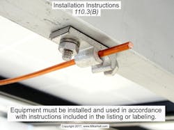
(B) Installation and Use. Equipment must be installed and used in accordance with any instructions included in the listing or labeling requirements, as shown in Fig. 1.
Author’s Comments: See the definitions of “labeling” and “listing” in Article 100.
Failure to follow product listing instructions, such as the torqueing of terminals and the sizing of conductors, is a violation of this Code rule.
(C) Product Listing (Certification). Product certification (testing, evaluation, and listing) must be performed by a recognized qualified testing laboratory in accordance with standards that achieve effective safety to comply with the NEC.
Note: OSHA recognizes qualified electrical testing laboratories that provide product certification that meets OSHA electrical standards.
Analysis:
Remanufactured Equipment. In a perfect world, all electrical equipment would be shiny and new, but that isn’t reality. Sometimes, older electrical equipment must continue to be used for many reasons — the most common of which are availability and cost. This often includes installing electrical equipment that isn’t new, but is instead reconditioned, refurbished, or remanufactured. This is commonly done with circuit breakers of obscure panels that haven’t been manufactured in decades. A new Informational Note points out that the inspector should not reject equipment based solely on the fact that it is remanufactured.
Listing. A new subsection (C), covering listing, was added. Although the definition of “listed” in Art. 100 states a testing laboratory that tests and lists products must be acceptable to the AHJ, it does little else in terms of regulating the listing agency. This makes sense because definitions aren’t supposed to contain rules. So who does the testing and listing, and what do they use as their basis of acceptance? Can I make my own company, test a product in a backyard shop by plugging it in, put a sticker on it, and call it listed? With the revisions in 2017 NEC, you cannot. Testing laboratories must be recognized as being qualified, and one way to locate this information is OSHA, which lists Nationally Recognized Testing Laboratories (NRTLs).
Change No. 2: Section 110.14 (Conductor Termination and Splicing)
A properly calibrated tool must be used when torqueing terminal connections.
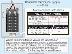
(D) Torque. Where tightening torque values are indicated on equipment or installation instructions, a calibrated torque tool must be used to achieve the indicated torque value, unless the equipment manufacturer provides an alternative method of achieving the required torque (Fig. 2).
Author’s comments: Conductors must terminate in devices that have been properly tightened in accordance with the manufacturer’s torque specifications included with equipment instructions. Failure to torque terminals can result in excessive heating of terminals or splicing devices due to a loose connection. A loose connection can also lead to arcing, which increases the heating effect and may also lead to a short circuit or ground fault. Any of these can result in a fire or other failure, including an arc-flash event. In addition, this is a violation of 110.3(B), which requires all equipment to be installed in accordance with listing or labeling instructions.
Analysis:
When electrical fires or failures occur, they usually occur at terminations — not in the middle of a cable or conductor. With that said, the rules in Sec. 110.14 are some of the most important in all of the Code. Studies have found that approximately 75% to 80% of conductor terminations are not installed correctly unless a torque measuring device, such as a torque wrench or screwdriver, is used. Approximately 60% of conductor terminations are not tight enough, and 20% are too tight — leaving about only 20% meeting the manufacturer’s torqueing requirements. This new rule requires that the installer use a properly calibrated tool for conductor terminations when a tightening torque is specified for the terminal by the manufacturer.
Enforcement of this new rule will prove challenging. Does the electrical inspector need to be on site during the terminations for verification of the tool being used? How will he or she know the tool is calibrated correctly? Has the tool been dropped since being calibrated and is therefore inaccurate? Should the inspector carry his or her own tools?
As with any new Code rule, this one might create growing pains, but we can all certainly agree on one thing: This rule is intended to increase safety by ensuring proper terminations. Let’s not lose sight of the big picture — electrical safety.
Change No. 3: Section 210.8 (GFCI Protection)
Appliance GFCI requirements were relocated to Sec. 422.5, measuring and GFCI requirements for receptacles near sinks were clarified, GFCI requirements for unfinished basement and non-dwelling receptacles were clarified, and new requirements were added for crawl spaces.
Ground-fault circuit interruption for personnel must be provided as required in Sec. 210.8(A) through (E). The GFCI device must be installed at a readily accessible location.
Note 2: See Sec. 422.5 for GFCI requirements for automotive vacuum machines, drinking water coolers, high-pressure spray washing machines, tire inflation machines provided for public use, and vending machines.
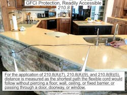
For the application of Sections 210.8(A)(7), 210.8(A)(9), and 210.8(B)(5), distance is measured as the shortest path the flexible cord would follow without piercing a floor, wall, ceiling, or fixed barrier, or passing through a door, doorway, or window (Fig 3).
(A) Dwelling Units. GFCI protection is required for 15A and 20A, 125V receptacles installed in the following locations:
(1) Bathroom Area. GFCI protection is required for 15A and 20A, 125V receptacles in the bathroom area of a dwelling unit.
(2) Garages and Accessory Buildings. GFCI protection is required for 15A and 20A, 125V receptacles in garages, and in grade-level portions of accessory buildings used for storage or work areas of a dwelling unit.
Author’s comments: A receptacle outlet is required in a dwelling unit attached garage [210.52(G)(1)], but a receptacle outlet isn’t required in an accessory building or a detached garage without power. If a 15A or 20A, 125V receptacle is installed in an accessory building, it must be GFCI-protected.
(3) Outdoors. GFCI protection is required for 15A and 20A, 125V receptacles located outdoors of dwelling units, including receptacles installed under the eaves of roofs.
Author’s comments: Each dwelling unit of a multifamily dwelling that has an individual entrance at grade level must have at least one GFCIâprotected receptacle outlet accessible from grade level located not more than 6½ ft above grade [210.52(E)(2)].
Balconies, decks, and porches that are attached to the dwelling unit and are accessible from inside the dwelling must have at least one GFCI-protected receptacle outlet accessible from the balcony, deck, or porch [210.52(E)(3)].
Exception: GFCI protection isn’t required for a receptacle that’s supplied by a branch circuit dedicated to fixed electric snow-melting, deicing or pipeline and vessel heating equipment, if the receptacle isn’t readily accessible and the equipment or receptacle has ground-fault protection of equipment (GFPE) [426.28 and 427.22].
(4) Crawl Spaces at or Below Grade Level. GFCI protection is required for 15A and 20A, 125V receptacles installed in crawl spaces at or below grade.
Author’s comments: The Code doesn’t require a receptacle to be installed in a crawl space, except when heating, air-conditioning, and refrigeration equipment is installed there [210.63].
(5) Unfinished Portions of Basements. GFCI protection is required for 15A and 20A, 125V receptacles located in unfinished portions or areas of a basement not intended for habitable rooms.
Exception: A receptacle supplying only a permanently installed fire alarm or burglar alarm system isn’t required to be GFCI protected [760.41(B) and 760.121(B)].
(6) Kitchen Countertop Surfaces. GFCI protection is required for 15A and 20A, 125V receptacles that serve countertop surfaces.
Author’s comments: See Sec. 210.52(C) for the location requirements of countertop receptacles.
(7) Sinks. GFCI protection is required for 15A and 20A, 125V receptacles located within 6 ft from the top inside edge of the bowl of the sink.
(8) Boathouses. GFCI protection is required for 15A and 20A, 125V receptacles located in a dwelling unit boathouse.
Author’s comments: The Code doesn’t require a 15A or 20A, 125V receptacle to be installed in a boathouse, but if one is installed, it must be GFCI-protected.
(9) Bathtubs or Shower Stalls. GFCI protection is required for 15A and 20A, 125V receptacles located within 6 ft of the outside edge of a bathtub or shower stall.
(10) Laundry Areas. GFCI protection is required for 15A and 20A, 125V receptacles installed in laundry areas.
(B) Other than Dwelling Units. GFCI protection is required for single-phase receptacles rated 50A or less not exceeding 150V to ground and 3-phase receptacles rated 100A or less not exceeding 150V to ground installed in the following locations:
(1) Bathrooms. GFCI protection is required for receptacles installed in bathrooms.
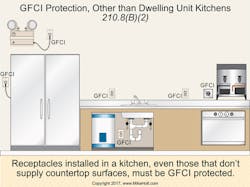
(2) Kitchens. GFCI protection is required for receptacles installed in a kitchen (Fig. 4).
(3) Rooftops. GFCI protection is required for receptacles installed on rooftops.
Author’s comments: A 15A or 20A, 125V receptacle outlet must be installed within 25 ft of heating, air-conditioning, and refrigeration equipment [210.63].
Exception No. 1: Rooftop receptacles are required to be readily accessible from the rooftop surface area.
(4) Outdoors. GFCI protection is required for receptacles installed outdoors.
(5) Sinks. GFCI protection is required for receptacles installed within 6 ft from the top inside edge of the bowl of the sink.
Exception No. 1: In industrial laboratories, receptacles used to supply equipment where removal of power would introduce a greater hazard aren’t required to be GFCI protected.
(6) Indoor Wet Locations. GFCI protection is required for receptacles installed indoors in wet locations.
(7) Locker Rooms. GFCI protection is required for receptacles installed in locker rooms with associated showering facilities.
(8) Garages. GFCI protection is required for receptacles installed in garages, service bays, and similar areas, other than show rooms and exhibition halls.
(9) Crawl Space Receptacle Outlets. GFCI protection is required for receptacles in crawl spaces.
(10) Unfinished Portions of Basements. GFCI protection is required for receptacles located in the unfinished portions of a basement.
(C) Boat Hoist — Dwelling Unit. GFCI protection is required for boat hoist outlets not exceeding 240V at dwelling unit locations.
(D) Dishwasher — Dwelling Unit. GFCI protection is required for outlets supplying dishwashers at a dwelling unit.
(E) Crawl Space Lighting Outlets—Dwelling. GFCI protection is required for 120V lighting outlets in crawl spaces in dwelling units.
Analysis:
Informational Note. GFCI requirements have been added to the NEC every Code cycle since 1971, and this edition is no exception. A new Informational Note was added, alerting the user to the fact that GFCI protection requirements for appliances are now contained in Sec. 422.5 instead of Sec. 210.8.
Measurement of 6-Ft Rule. Where GFCI protection is required within 6 ft of a sink, how were we to measure the dimension? The change to this edition of the NEC makes it clear that it’s measured as the path a cord would follow without piercing a wall, door, window, or similar object.
Unfinished Basements. Revised GFCI requirements for receptacles in dwelling unit unfinished basements clarify that unfinished portions of basements require GFCI protection. This is hardly a new concept, but by removing the language specifying “storage areas, work areas, and the like,” there’s less room for interpretation and therefore less room for confusion. While this isn’t much of a change, any opportunity to remove vagueness is worth at least considering, if not changing.
Sinks. Receptacles within 6 ft of dwelling unit sinks require GFCI protection. How is this to be measured? The Code already clarified that it’s the path a cord would take, but where do we begin the measurement? The NEC is now clear in that we begin at the inside edge of the bowl of the sink and measure 6 ft.
GFCI Protection. The 2017 Code now requires GFCI protection for single-phase receptacles rated 50A or less, not exceeding 150V to ground and 3-phase receptacles rated 100A or less not exceeding 150V to ground installed in non-dwelling unit locations.
Crawl Spaces. Added GFCI protection requirements for receptacles in crawl spaces and in unfinished basements of other than dwellings. While crawl spaces and unfinished basements are certainly more common in residential buildings, they do exist in commercial buildings as well. Because the GFCI rules are driven by location, it makes sense that the same locations requiring GFCI protection in a dwelling crawl space be mandated in commercial occupancies as well.
Lighting Outlet GFCI Protection. The 2017 Code now covers GFCI protection for lighting outlets in crawl spaces. It’s easy to visualize people crawling around under their houses and having their back (or head) break a light in the crawl space, or to install a receptacle adapter in the screw shell of the lampholder. It doesn’t take much more imagination to think of that person getting shocked. Add in a dirt floor, and you really have a recipe for disaster. Thus, adding GFCI protection for these lighting outlets is a great idea.
Change No. 4: Section 210.12 (Arc-Fault Circuit-Interrupter Protection)
The AFCI requirements have been greatly expanded.
Arc-fault circuit-interrupter protection must be provided in accordance with Sec. 210.12(A), (B), and (C). AFCI devices must be installed in readily accessible locations.
(A) Required Locations. A listed combination AFCI breaker is required for all 15A or 20A, 120V branch circuits in dwelling units supplying outlets or devices in kitchens, family rooms, dining rooms, living rooms, parlors, libraries, dens, bedrooms, sunrooms, recreation rooms, closets, hallways, laundry areas, or similar rooms or areas.
(B) Dormitory Units. A listed combination AFCI breaker is required for all 15A or 20A, 120V branch circuits for outlets and devices in dormitory unit bedrooms, living rooms, hallways, closets, bathrooms, and similar rooms in accordance with 210.12(A).
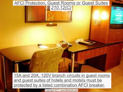
(C) Guest Rooms and Guest Suites. A listed combination AFCI breaker is required for all 15A or 20A, 120V branch circuits supplying outlets and devices in guest rooms and guest suites of hotels and motels (Fig. 5).
(D) Branch-Circuit Extensions or Modifications in Dwelling Units and Dormitory Units. Where 15A or 20A, 120V branch-circuit wiring is modified, replaced, or extended in a dwelling unit or dormitory where AFCI protection is required [210.12(A)], the modified, replaced, or extended branch-circuit wiring must be AFCI protected by one of the following methods:
(1) A listed combination AFCI circuit breaker.
(2) A listed AFCI receptacle located at the first receptacle outlet of the branch circuit.
Exception: AFCI protection isn’t required for extension wiring that’s less than 6 ft in length if no outlets or devices are added.
Analysis:
AFCI protection is now required for guest rooms and suites of hotels and motels. This seems to be the progression of Code rules, such as the tamper-resistant receptacles required in Sec. 406.12. Because these areas are very similar in their use to dwelling units, this new rule was accepted.
The requirement for updating the electrical system when adding or modifying wiring was extended to dormitories. The NEC is often three years behind in making new allowances, and this will be the case as long as humans are responsible for the Code. Considering that there are typically 3,000 to 5,000 proposals (now called “public input”) to change the NEC, things are going to slip through the cracks. Why not require the same rules and the same exception to all areas requiring AFCI protection?
Change No. 5: Section 210.71 (Meeting Rooms)
New rules require receptacle outlets for meeting rooms in commercial occupancies.
210.71 Meeting Rooms
(A) General. Meeting rooms not larger than 1,000 sq ft must have receptacle outlets for 15A or 20A, 125V receptacles in accordance with 210.71(B). Where a room or space is provided with a movable partition(s), the room size must be determined with the partition in the position that results in the smallest size meeting room.
Note 1: Meeting rooms are typically designed or intended for the gathering of seated occupants for conferences, deliberations, or similar purposes, where portable electronic equipment such as computers, projectors, or similar equipment is likely to be used.
Note 2: Examples of rooms that aren’t meeting rooms within the scope of 210.70 include auditoriums, school rooms, and coffee shops.
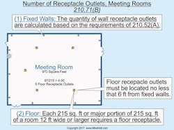
(B) Number of Receptacle Outlets Required. Meeting room receptacle outlets are located by the designer or building owner, and the number of receptacle outlets are determined in accordance with (B)(1) and (2) as follows (Fig. 6).
(1) Fixed Walls. The quantity of wall receptacle outlets is calculated on the basis of a receptacle outlet installed so that no point along the floor line is more than 6 ft, measured horizontally from a receptacle outlet in accordance with 210.52(A).
(2) Floor. A floor receptacle outlet is required for each 215 sq ft or major portion of a 215-sq-ft meeting room space having a width of 12 ft or more. The floor receptacle outlets must be located no less than 6 ft from fixed walls.
Note 1: Receptacle floor boxes must be listed for the purpose [314.27(B)].
Note 2: See Article 518 for assembly occupancies designed for 100 or more persons.
Analysis:
Meeting rooms are breeding grounds for cord usage. When teaching a seminar, I always need an extension cord to reach my laptop and projector. There are often people in the audience who have laptops and no way of plugging them in, short of running a 25-ft extension cord across a walkway. During other types of meetings, every participant typically has and needs a laptop as well. It’s not uncommon to see extension cords and daisy-chained relocatable power taps (plug strips) all over the floor. This requirement was added proactively, as there haven’t been any injuries or fires reported…yet. With this new rule, we’ll hopefully never have any such reports. Of course, there are other arguments to discuss as well. I’ve personally seen people step on cords that were being used at floor receptacles (including my own laptop cord). When this happens, the person can trip or roll an ankle, and the attachment plug on the cord can be damaged. This new requirement only applies to spaces not exceeding 1,000 sq ft. What’s magical about 1,000 sq ft? If this is a problem for smaller meeting rooms, why isn’t it a problem for larger ones as well? There are concerns about what is and what isn’t a meeting room; hence, the inclusion of two Informational Notes. Meeting rooms are where people have meetings. Meeting rooms aren’t where people meet, such as a coffee shop. Trust me — this rule is going to cause many unintended problems.
Change No. 6: Section 250.66 (Sizing Grounding Electrode Conductors)
The text of “sole connection” for rods, pipes, rings, and concrete-encased electrodes was clarified.
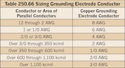
Except as permitted in (A) through (C), the grounding electrode conductor must be sized in accordance with Table 250.66 (see Table 1).
(A) Rod. If the grounding electrode conductor or bonding jumper connects to one or more ground rods [250.52(A)(5)] and doesn’t connect to another type of electrode that requires a larger conductor, the grounding electrode conductor isn’t required to be larger than 6 AWG copper.
(B) Concrete-Encased Grounding Electrode. If the grounding electrode conductor or bonding jumper is connected to one or more concrete-encased electrodes [250.52(A)(3)] and doesn’t connect to another type of electrode that requires a larger size conductor, the grounding electrode conductor isn’t required to be larger than 4 AWG copper.
Analysis:
Although many people don’t read the rules in Sec. 250.66, they allow for smaller grounding electrode conductors for driven rods, concrete-encased electrodes, and ground rings than those in Table 250.66. These smaller grounding electrode conductors, as compared to Table 250.66, can only be used when the grounding electrode conductor is the “sole connection” to these electrodes. What exactly does “sole connection” mean? In this edition of the Code, we won’t be asking this question any longer because that language was replaced. We can use the smaller grounding electrode conductors if they don’t also connect to an electrode requiring a larger grounding electrode conductor. This was the intent all along, and you could easily argue that the NEC was already clear on this. Now it’s even more so, and that’s always worth the effort.
Change No. 7: Section 310.15 (Conductor Ampacity)
As always, many changes to the rules for establishing conductor ampacities have been made, including requirements for cable bundling, rooftop temperature correction, and dwelling service conductor sizing.
(A) General Requirements.
(1) Tables for Engineering Supervision. The ampacity of a conductor can be determined either by using the tables in accordance with Sec. 310.15(B), or under engineering supervision as provided in 310.15(C).
Note 1: Ampacities provided by this section don’t take voltage drop into consideration. See Sec. 210.19(A) Note 4, for branch circuits and Sec. 215.2(D) Note 2, for feeders.
(2) Conductor Ampacity — Lower Rating. Where more than one ampacity applies for a given circuit length, the lowest ampacity value is to be used for the circuit.
Exception: When different ampacities apply to a length of conductor because of temperature correction [310.15(B)(2)(a)] or conductor bundling [310.15(B)(3)(a)], the higher ampacity can apply for the entire circuit if length of the corrected or adjusted ampacity doesn’t exceed the lesser of 10 ft or 10% of the length of the total circuit.
(3) Insulation Temperature Limitation. Conductors aren’t permitted to be used where the operating temperature exceeds that designated for the type of insulated conductor involved.
Note 1: The insulation temperature rating of a conductor [Table 310.104(A)] is the maximum temperature a conductor can withstand over a prolonged time period without serious degradation. The main factors to consider for conductor operating temperature include:
(1) Ambient temperature may vary along the conductor length as well as from time to time [Table 310.15(B)(2)(a)].
(2) Heat generated internally in the conductor — load current flow.
(3) The rate at which generated heat dissipates into the ambient medium.
(4) Adjacent load-carrying conductors have the effect of raising the ambient temperature and impeding heat dissipation [Table 310.15(B)(3)(a)].
Note 2: See Sec. 110.14(C)(1) for the temperature limitation of terminations.
(B) Ampacity Table. The allowable conductor ampacities listed in Table 310.15(B)(16) are based on conditions where the ambient temperature isn’t over 86°F, and no more than three current-carrying conductors are bundled together.
The temperature correction [310.15(B)(2)(a)] and adjustment factors [310.15(B)(3)(a)] apply to the conductor ampacity, based on the temperature rating of the conductor insulation in accordance with Table 310.15(B)(16).
(2) Conductor Ampacity Ambient Temperature Correction. When conductors are installed in an ambient temperature other than 78°F to 86°F, the ampacities listed in Table 310.15(B)(16) must be corrected in accordance with the multipliers listed in Table 310.15(B)(2)(a).
(3) Conductor Ampacity Adjustment.
(a) Four or More Current-Carrying Conductors. Where four or more current-carrying power conductors are within a raceway longer than 24 in. [310.15(B)(3)(a)(3)], or where cables are bundled for a length longer than 24 in., the ampacity of each conductor must be reduced in accordance with Table 310.15(B)(3)(a).
(1) Conductor ampacity adjustment of Table 310.15(B)(3)(a) doesn’t apply to conductors installed in cable trays, Sec. 392.80 applies.
(2) Conductor ampacity adjustment of Table 310.15(B)(3)(a) doesn’t apply to conductors in raceways having a length not exceeding 24 in.
(4) Conductor ampacity adjustment of Table 310.15(B)(3)(a) doesn’t apply to conductors within Type AC or Type MC cable under the following conditions:
a. The cables don’t have an outer jacket,
b. Each cable has no more than three current-carrying conductors,
c. The conductors are 12 AWG copper, and
d. No more than 20 current-carrying conductors (ten 2-wire cables or six 3-wire cables) are installed without maintaining spacing for a continuous length longer than 24 in.
Exception to (4): A 60% adjustment factor applies if the number of current-carrying conductors in these cables that are stacked or bundled longer than 24 in. without maintaining spacing exceeds 20.
(c) Raceways and Cables Exposed to Sunlight on Rooftops. Where raceways or cables are exposed to direct sunlight and located less than 7⁄8 in. above the roof, a temperature adder of 60°F/33°C is to be added to the outdoor ambient temperature to determine the ambient temperature for the application of the ampacity correction in accordance with Table 310.15(B)(2)(a).
Exception: Type XHHW-2 insulated conductors aren’t subject to the temperature adder of 60°F/33°C.
Note 1: See the ASHRAE Handbook — Fundamentals (www.ashrae.org) as a source for the ambient temperatures in various locations.
Author’s comments: This rule requires the ambient temperature used for ampacity correction to be adjusted where conductors or cables are installed within a raceway or cable on or above a rooftop, and the raceway is exposed to direct sunlight. The reasoning is that the air inside raceways and cables that are in direct sunlight is significantly hotter than the surrounding air, and appropriate ampacity corrections must be made in order to comply with Sec. 310.10.
(5) Neutral Conductors.
(a) The neutral conductor of a 3-wire, single-phase, 120/240V system, or 4-wire, 3-phase, 120/208V or 277/480V wye-connected system, isn’t considered a current-carrying conductor for conductor ampacity adjustment of 310.15(B)(3)(a).
(b) The neutral conductor of a 3-wire circuit from a 4-wire, 3-phase, 120/208V or 277/480V wye-connected system is considered a current-carrying conductor for conductor ampacity adjustment of 310.15(B)(3)(a).
Author’s comments: When a 3-wire circuit is supplied from a 4-wire, 3-phase, 120/208V or 277/480V wye-connected system, the neutral conductor carries approximately the same current as the ungrounded conductors.
(c) The neutral conductor of a 4-wire, 3-phase, 120/208V or 277/480V wye-connected system is considered a current-carrying conductor for conductor ampacity adjustment of 310.15(B)(3)(a) if more than 50% of the neutral load consists of nonlinear loads.
Author’s comments: Nonlinear loads supplied by a 4-wire, 3-phase, 120/208V or 277/480V wye-connected system can produce unwanted and potentially hazardous odd triplen harmonic currents (3rd, 9th, 15th, and so on) that can add on the neutral conductor. To prevent fire or equipment damage from excessive harmonic neutral current, the designer should consider increasing the size of the neutral conductor or installing a separate neutral for each phase. For more information, visit www.MikeHolt.com, click on the “Technical” link, then the “Power Quality” link. Also see 210.4(A) Note, 220.61 Note 2, and 450.3 Note 2.
(6) Grounding Conductors. Grounding and bonding conductors aren’t considered current carrying.
(7) Single-Phase Dwelling Services and Feeders.
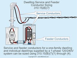
120/240V System. For dwelling units, service and feeder conductors supplied by a single-phase, 120/240V system can be sized in accordance with the requirements contained in 310.15(B)(7)(1) through (4), as shown in Fig. 7.
120/208V System. For dwelling units, service and feeder conductors supplied by a single-phase, 120/208V system can be sized in accordance with the requirements contained in 310.15(B)(7)(1) through (3).
(1) Service Conductors. Ungrounded service conductors supplying the entire load of a one-family dwelling or an individual dwelling unit in a two-family or multifamily dwelling can have the conductor ampacity sized to 83% of the service overcurrent protection device rating.
Author’s comments: Sec. 310.15(B)(7) can’t be used for service conductors for two-family or multifamily dwelling buildings.
(2) Feeder Conductors. Ungrounded feeder conductors not over 400A supplying the entire load of a one-family dwelling, or an individual dwelling unit in a two-family or multifamily dwelling, can have the ungrounded feeder conductors sized to 83 percent of the feeder overcurrent protection device rating.
Author’s comments: Section 310.15(B)(7)(2) can’t be used to size feeder conductors where a feeder doesn’t carry the entire load of the dwelling unit, except as permitted in 310.15(B)(7)(3).
(3) Feeder Conductors Not Greater Than. Feeder conductors for an individual dwelling unit aren’t required to be larger than the service conductors.
(4) Neutral Conductors. For one-family dwellings and individual dwelling units of two-family and multifamily dwellings, service and feeder neutral conductors supplied by a single-phase, 120/240V system can be smaller than the ungrounded conductors, provided that the requirements of Sec. 220.61 and Sec. 230.42 for services and Sec. 220.61 and Sec. 215.2 for feeders are met.
Caution: Because the service neutral conductor is required to serve as the effective ground-fault current path, it must be sized so it can safely carry the maximum fault current likely to be imposed on it [110.10 and 250.4(A)(5)]. This is accomplished by sizing the neutral conductor in accordance with Table 250.102(C), based on the area of the largest ungrounded service conductor [250.24(C)(1)].
Where conductor ampacity correction or adjustment factors are required by Sec. 310.15(B)(2) or (3), we’re to use the ampacity associated with the temperature rating of the conductor in accordance with Table 310.15(B)(16).
Note 1: The service or feeder ratings addressed by this section are based on the standard ampacity ratings from Sec. 240.6(A).
Analysis:
Bundling of Cables. There’s been an allowance to ignore ampacity adjustments for up to twenty 12 AWG 3-conductor Type MC or AC cables without a nonmetallic outer covering for a long time. One of the factors that allows for this permission is that these cables have ridges from the spiral interlocking metal armor, which means that when the cables are touching each other there’s actually space between them. This permissive allowance is still in place but was rewritten as an Exception without changing any of the technical requirements or allowances.
Rooftop Wiring Methods. Of much greater interest is a change made to Sec. 310.15(B)(3)(c) for cables and raceways on rooftops. Since its inclusion in the 2011 NEC, few rules have been more controversial than this one. Temperatures on a rooftop are higher than they are at grade level; nobody denies this. However, if this is a real issue in the world of electrical installations, why haven’t any buildings burned down because of conductor failures from excessive ambient heat? If there were actual incidents of failures, there would be interested parties telling us all about it, mainly to require larger conductors. Think about it. If you were a conductor manufacturer, wouldn’t you be on the lookout for points of failure so you could lobby for rules mandating larger wires? Of course you would. Well, there have never been fires on rooftops that were caused by excessive ambient heat. This requirement was poorly substantiated from the start, and now it’s pretty much gone. Instead of having to apply a correction temperature adder for wiring on a rooftop, we only have to deal with this if the wiring method is within 7⁄8 of an inch from the roof. This should be very easy to work around.
Dwelling Unit Conductor Sizing. Section 310.15(B)(7) has seen a tremendous number of changes over the last few Code cycles. The allowance for smaller service and feeder conductors for dwellings has never been present for 120/208V systems — until now. In a 120/240V system, when a circuit consists of two ungrounded conductors and a shared neutral, the neutral will carry the difference in current between the ungrounded conductors. For example, 80A on line 1 and 60A on line 2 will result in 20A on the neutral, or 80A on each phase will result in zero current on the neutral conductor. This isn’t the case for a 120/208V system. With two ungrounded conductors and a shared neutral, the neutral will carry a substantial amount of current. If we have 80A on line 1 and 80A on line 2, the neutral will carry 80A! This was the reason 120/208V systems weren’t permitted to take advantage of the reduced sizing allowances of this section. In this cycle, this requirement was relaxed. We’ll see how it turns out, but I have a feeling it will be just fine. The NEC load calculations for dwellings are still much higher than the actual consumption of power, so it seems there’s probably enough safety already factored into the design.
Change No. 8: Section 312.8 (Switch and Overcurrent Protection Device Enclosures)
The rules for sufficient conductor space within cabinets have been revised to deal with power monitoring equipment.
Cabinets are permitted to contain overcurrent protection devices and other wiring and equipment as provided in (A) and (B).
(A) Splices, Taps, and FeedâThrough Conductors. The wiring space within cabinets can be used for conductors feeding through, spliced, or tapping where all of the following conditions are met:
(1) The area of conductors at any cross section doesn’t exceed 40% of the cross-sectional area of the space.
(2) The area of conductors, splices, and taps at any cross section doesn’t exceed 75% of the cross-sectional area of that space.
(3) A permanently affixed warning label having sufficient durability to withstand the environment involved and comply with Sec. 110.21(B), must be applied on the cabinet to identify the location of the disconnecting means for the feed-through conductors.
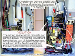
(B) Power Monitoring Equipment. The wiring space within cabinets can contain power monitoring equipment where all of the following conditions are met:
(1) The power monitoring equipment is identified as a field-installable accessory as part of listed equipment, or a listed kit for field installation in the overcurrent protection device enclosures (Fig. 8).
(2) The area of all conductors, splices, taps, and equipment at any cross section doesn’t exceed 75 percent of the cross-sectional area of that space.
Analysis:
As technology evolves, so must the NEC. Energy management and power monitoring systems are becoming more popular in today’s modern buildings, and the Code has a bit of catching up to do. This section has long given requirements on enclosures containing splices and feed-through conductors, and it even made mention of “other equipment” in the enclosure. Now the “other equipment” being discussed is clear and has clear rules. Power
monitoring equipment can be, and often is, installed in a cabinet containing overcurrent protection devices. According to the 2017 NEC, when this is the case, the equipment must be identified as a field-installable accessory, or it must be listed for installation in a switch or overcurrent protection device enclosure. The total area consumed by the equipment and its associated wiring, splices, and so forth is still limited to 75% of the cross-sectional area of that space.
Change No. 9: Section 314.28 (Sizing Boxes and Conduit Bodies — Conductors 4 AWG and Larger)
The allowance for using conduit bodies smaller than generally required was clarified, and power distribution blocks on the supply side of the service are now allowed (if listed for the location).
Boxes and conduit bodies containing conductors 4 AWG and larger that are required to be insulated must be sized so the conductor insulation won’t be damaged.
Author’s comments: The requirements for sizing boxes and conduit bodies containing conductors 6 AWG and smaller are contained in Sec. 314.16. If conductors 4 AWG and larger enter a box or other enclosure, a fitting that provides a smooth, rounded, insulating surface, such as a bushing or adapter, is required to protect the conductors from abrasion during and after installation [300.4(G)].
(A) Minimum Size. For raceways containing conductors 4 AWG and larger, the minimum dimensions of boxes and conduit bodies must comply with the following:
(1) Straight Pulls. The minimum distance from where the conductors enter the box or conduit body to the opposite wall isn’t permitted to be less than eight times the trade size of the largest raceway.
(2) Angle Pulls, U Pulls, or Splices.
Angle Pulls. The distance from the raceway entry of the box or conduit body to the opposite wall isn’t permitted to be less than six times the trade size of the largest raceway, plus the sum of the trade sizes of the remaining raceways on the same wall and row.
U Pulls. When a conductor enters and leaves from the same wall of the box, the distance from where the raceways enter to the opposite wall isn’t permitted to be less than six times the trade size of the largest raceway, plus the sum of the trade sizes of the remaining raceways on the same wall and row.
Splices. When conductors are spliced, the distance from where the raceways enter to the opposite wall isn’t permitted to be less than six times the trade size of the largest raceway, plus the sum of the trade sizes of the remaining raceways on the same wall and row.
Rows. If there are multiple rows of raceway entries, each row is calculated individually and the row with the largest distance must be used.
Distance Between Raceways. The distance between raceways enclosing the same conductor isn’t permitted to be less than six times the trade size of the largest raceway, measured from the raceways’ nearest edge to nearest edge.
Exception: When conductors enter an enclosure with a removable cover, the distance from where the conductors enter to the removable cover isn’t permitted to be less than the bending distance as listed in Table 312.6(A) for one conductor per terminal.
(3) Smaller Dimensions Conduit Bodies. Conduit bodies sized smaller than required by Sec. 314.28(A)(1) and Sec. 314.28(A)(2) are permitted to be used if the cross-sectional area of the conductors installed don’t exceed the cross-sectional area of the number of conductors and size of conductors marked on the conduit body.
Note: Unless otherwise specified, the fill markings on the conduit body are based on conductors with Type XHHW insulation.
(B) Conductors in Pull or Junction Boxes. Pull boxes or junction boxes with any dimension over 6 ft must have all conductors cabled or racked in an approved manner.
(C) Covers. Pull boxes, junction boxes, and conduit bodies must have a cover suitable for the conditions. Metal covers must be connected to an equipment grounding conductor of a type recognized in Sec. 250.118, in accordance with Sec. 250.110 [250.4(A)(3)].
(E) Power Distribution Block. Power distribution blocks must comply with the following:
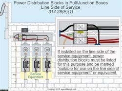
(1) Installation. Power distribution blocks must be listed; if installed on the line side of the service equipment, power distribution blocks must be listed and marked “suitable for use on the line side of service equipment” or equivalent (Fig. 9).
(2) Size. Be installed in a box not smaller than required by the installation instructions of the power distribution block.
(3) Wire-Bending Space. The junction box is sized so that the wire-bending space requirements of Sec. 312.6 can be met.
(4) Live Parts. Exposed live parts on the power distribution block aren’t present when the junction box cover is removed.
(5) Through Conductors. Where the junction box has conductors that don’t terminate on the power distribution block(s), the through conductors must be arranged so the power distribution block terminals are unobstructed following installation.
Analysis:
Conduit Body. When it comes to sizing conduit bodies, the general rule is that they must comply with the requirements of pull junction boxes — like a length of six times the diameter of the raceway entry. However, the Code permits conduit bodies to be smaller than those dimensions when marked to accommodate a specific size and number of conductors. This makes sense, until you consider the fact that not all conductors have the same outside diameter because not all of them have the same insulation. Revised text provides guidance on how to manage this application. The 2017 NEC requires the conduit body size to be based on XHHW insulation, which is one of the thicker insulations in use today.
Power Distribution Blocks. When power distribution blocks are installed on the supply side of the service disconnect, they must be marked that they’re suitable for that application. While that might sound like a strange rule, consider the fact that they weren’t allowed on the supply side at all — until now.
Change No. 10: Section 376.20 (Conductors Connected in Parallel)
A new requirement for grouping parallel conductors was added.
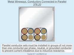
376.20 Conductors Connected in Parallel. Where conductors are installed in parallel as permitted in 310.10(H), the parallel conductor sets must be installed in groups consisting of not more than one conductor per phase, or neutral conductor to prevent current imbalance in the paralleled conductors due to inductive reactance (Fig. 10).
Analysis:
The concept of grouping the ungrounded and grounded conductors of a circuit together has been in the NEC for about 80 years. It’s repeated multiple times throughout the Code, including three separate occurrences in Art. 300 alone. It really is that important. The requirement for grouping parallel conductors in wireways was added during this cycle. According to Code Making Panel No. 8, there have been documented conductor failures in metal wireways because parallel conductors weren’t grouped together.
Change No. 11: Section 400.12 (Uses Not Permitted)
Changes attempt to clarify the restriction on cord use above a suspended ceiling; but, unfortunately, the attempt failed.
400.12 Uses Not Permitted
Unless specifically permitted in 400.10, flexible cords sets (extension cords) and power-supply cords aren’t permitted for the following:
(1) Flexible cords sets (extension cords) and power-supply cords aren’t permitted to be a substitute for the fixed wiring of a structure.
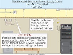
(2) Flexible cords sets (extension cords) and power-supply cords aren’t permitted to be run through holes in walls, structural ceilings, suspended or dropped ceilings, or floors (Fig. 11).
(3) Flexible cords sets (extension cords) and power-supply cords aren’t permitted to be run through doorways, windows, or similar openings.
(4) Flexible cords sets (extension cords) and power-supply cords aren’t permitted to be attached to building surfaces.
(5) Flexible cords sets (extension cords) and power-supply cords aren’t permitted to be concealed by walls, floors, or ceilings, or located above suspended or dropped ceilings.
Exception: Flexible cords can be located above suspended or dropped ceilings if installed in a metal enclosure in accordance with 300.22(C)(3).
(6) Flexible cords sets (extension cords) and power-supply cords aren’t permitted to be installed in raceways, except as permitted by 400.17 for industrial establishments where the conditions of maintenance and supervision ensure that only qualified persons will service the installation.
(7) Flexible cords sets (extension cords) and power-supply cords aren’t permitted to be where subject to physical damage.
Author’s Comment: Even cords listed as “extra-hard usage” must not be used where subject to physical damage.
Analysis:
Cords above a suspended ceiling have been the bane of both inspectors and electricians ever since the invention of the projector. Nearly every office building and every school has a projector (or dozens of them) installed above a suspended ceiling. In previous editions of the Code, it wasn’t clear that the power-supply cord for a projector had to follow the restrictions on its use above and through a suspended ceiling. The 2017 NEC allows a power supply above a suspended ceiling if installed in a metal enclosure. Before you get too excited, this is for a very specific type of equipment enclosure, not a metal raceway. The problem with the 2017 changes to this section is that now it doesn’t apply to “flexible cords;” it only applies to extension cords and power-supply cords. The renumbering of this section (from 400.8 and 400.10), uses permitted and uses not permitted, is also worth noting as they’ve now been changed to 400.10 and 400.12 to mirror Chapter 3’s uses permitted and uses not permitted sections.
Change No. 12: Section 404.2 (Switch Connections)
An attempt was made to clarify when a neutral is required at a switch.
(A) Three-Way and Four-Way Switches. Wiring for 3-way and 4-way switching must be done so that only the ungrounded conductors are switched.
Author’s Comment: In other words, the neutral conductor must not be switched. The white insulated conductor within a cable assembly can be used for single-pole, 3-way, or 4-way switch loops if it’s permanently re-identified to indicate its use as an ungrounded conductor at each location where the conductor is visible and accessible [200.7(C)(2)].
If a metal raceway or metal-clad cable contains the ungrounded conductors for switches, the wiring must be arranged to avoid heating the surrounding metal by induction. This is accomplished by installing all circuit conductors in the same raceway in accordance with Sec. 300.3(B) and Sec. 300.20(A), or ensuring that they’re all within the same cable.
Exception: A neutral conductor isn’t required in the same raceway or cable with travelers and switch leg (switch loop) conductors.
(B) Switching Neutral Conductors. Only the ungrounded conductor can be used for switching, and the grounded [neutral] conductor isn’t permitted to be disconnected by switches or circuit breakers.
Exception: A switch or circuit breaker can disconnect a grounded circuit conductor where it disconnects all circuit conductors simultaneously.
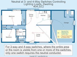
(C) Switches Controlling Lighting Loads. Switches controlling line-to-neutral lighting loads must have a neutral conductor installed at a switch serving bathrooms, hallways, stairways, or rooms suitable for human habitation or occupancy as defined in the applicable building code.
Where 3âway and 4âway switches are visible in a room, only one of the switches requires a neutral conductor (Fig. 12).
A neutral conductor isn’t required under any of the following conditions:
(1) Where conductors enter the box through a raceway with sufficient cross-sectional area to accommodate a neutral conductor.
(2) Where the switch box can be accessed to add or replace a cable without damaging the building finish.
(3) Snap switches with integral enclosures [300.15(E)].
(4) Where the lighting is controlled by automatic means.
(5) Switches controlling receptacles.
Effective January 1, 2020, the neutral conductor must be run to any replacement switch that requires line-to-neutral voltage [404.22] to operate the electronics of the switch in the standby mode.
Exception: A neutral conductor isn’t required for replacement switches installed in locations wired prior to the adoption of Sec. 404.2(C) where the neutral conductor can’t be extended without removing finish materials. The number of electronic lighting control switches without a neutral conductor on a branch circuit must not exceed five switches, and the number connected to any feeder must not exceed twenty-five switches.
Note: The purpose of the neutral conductor at a switch is to complete a circuit path for electronic lighting control devices that require a neutral conductor.
Analysis:
Ever since this rule was added in the 2011 NEC, it’s been hotly debated. Before getting upset at the Code language, challenge yourself to write a rule that addresses this issue — one that’s clear, concise, and not subject to interpretation. It isn’t easy at all. The concept is that we need a neutral at switch locations for line-to-neutral lighting loads, such as 120V or 277V lighting. This ensures we have a neutral if we install an electronic switch that requires one for proper operation. Everyone will agree that switches are becoming more complex as technology evolves. Yesterday’s light switch turned the lights on and off, but today’s switch dims the lights, checks for movement, and sometimes performs tasks like turning on computers, raising and lowering projector screens, and all sorts of other things. Smart electronic switches need a return path to the source for proper operation. In the past, the NEC permitted the equipment grounding conductor to be used for the return path.
Changes to this edition of the Code clarify that if line-to-neutral lighting is controlled by multiple switch locations (like a set of 3-way switches) the neutral is only required at one switch location. In 2014, it wasn’t required at all. The 2014 NEC included a major error by requiring the neutral at switches to be located in “habitable space,” which meant that no commercial buildings needed to comply with this rule. To address this issue, the Code now says that we need a neutral in areas “suitable for habitation or occupancy.” Problem solved.
Change No. 13: Section 404.22 (Electronic Lighting Switches)
A new rule requires electronic switch manufacturers to use a neutral for return current, not the equipment grounding conductor.
404.22 Electronic Lighting Switches
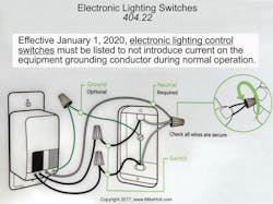
Effective January 1, 2020, electronic lighting control switches must be listed to not introduce current on the equipment grounding conductor during normal operation (Fig. 13).
Exception: Electronic lighting control switches that put current on the equipment grounding conductor [404.2(C) Ex] must be listed and marked for use only for replacement or retrofit applications.
Analysis:
As discussed in Sec. 404.2(C), using the equipment grounding conductor as a return path is a practice that we’ve been trying to eliminate for more than half a century. This new requirement carries an effective date of Jan. 1, 2020. Electricians shouldn’t really be caught off guard by this rule, as 404.2(C) requires a neutral at most switch locations for this very reason.
Change No. 14: Section 406.12 (Tamper-Resistant Receptacles)
The locations requiring tamper-resistant receptacles have been expanded, as have the types of receptacles requiring such protection.
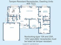
Nonlocking-type 15A and 20A, 125V and 250V receptacles in the following areas must be listed as tamper resistant:
Author’s Comment: On a tamper-resistant receptacle, inserting an object into one side of the receptacle doesn’t open the internal tamperâresistant shutter. Simultaneous pressure from a 2- or 3-pronged plug is required for insertion.
(1) Dwelling unit areas specified in Sec. 210.52 and Sec. 550.13 (Fig. 14)
(2) Hotel and motel guest rooms and guest suites
(3) Child care facilities
Author’s Comment: A child care facility is a building or portions thereof used for educational, supervision, or personal care services for five or more children seven years in age or less [406.2].
(4) Preschools and elementary education facilities
(5) Business offices, corridors, waiting rooms and the like in clinics, medical and dental offices, and outpatient facilities.
(6) Places of waiting transportation, gymnasiums, skating rinks, and auditoriums
(7) Dormitories
Note: Receptacle types covered by this requirement are identified as 5â15, 5â20, 6â15, and 6â20 in NEMA WD 6, Wiring Devices — Dimensional Specifications.
Exception to (1) through (7): Receptacles in the following locations aren’t required to be tamper resistant:
(1) Receptacles located more than 5½ ft above the floor.
(2) Receptacles that are part of a luminaire or appliance.
(3) A receptacle located within dedicated space for an appliance that in normal use isn’t easily moved from one place to another.
(4) Nongrounding receptacles used for replacements as permitted in Sec. 406.4(D)(2)(a).
Analysis:
Next time you find yourself at a grocery store, hardware store, or just about any store short of a gas station, notice how many plastic receptacle inserts there are. Consumers want more protection than what a standard receptacle provides.
Tamper-resistant receptacles were introduced in the 2008 Code for dwelling units, and this requirement was expanded in 2011 to include child care facilities, hotels, and motels. Not much changed in the 2014 NEC, but the 2017 edition is very different. The logic is that if 125V receptacles are dangerous to children, then 250V receptacles are as well. The 2017 Code adds a requirement that 15A and 20A, 250V receptacles also must be tamper-resistant, although it seems likely that many of these receptacles will be the exception by being installed in a location where the receptacle is covered by an appliance or other piece of equipment. It’s worth emphasizing that this rule is only for 15A and 20A receptacles, so those for ranges or dryers need not be tamper-resistant.
Several locations where tamper-resistant receptacles will now be required have been added to the list of areas requiring protection. Preschools and elementary schools are now included. While it may seem that these areas already required tamperâresistant receptacles, since they meet the definition of “child care facilities,” not all areas of a school needed to comply. The definition of a child care facility is a building or portion of a building where five or more children under the age of eight receive care, education, and so forth. This meant that some of the classrooms in a kindergarten through sixth-grade school met the definition but others didn’t. The sixth-grade classroom doesn’t need tamper-resistant protection, but the first-grade classroom does. The offices of the school staff don’t need tamper-resistant protection, but lunch areas do. One of the problems that needed to be addressed was that classrooms often change in terms of grade level. Yesterday, this room housed fifth graders; today it houses second graders. To alleviate this problem, the entire school must now meet the requirements. In addition, business offices, corridors, waiting rooms, and similar areas in medical and dental offices, and outpatient facilities now require tamper-resistant protection. They’re also required in dormitories, waiting areas in areas described in Art. 518 (places of assembly), gymnasiums, skating rinks, and auditoriums.
Tamper-resistance expansion was added due to a report issued by the Consumer Product Safety Commission (CPSC), indicating that the most common areas for shocks due to inserting objects in receptacles is the home (already covered) followed by “unknown” and schools, then sports and recreation facilities and “other public property.” Do you get the feeling that in the near future all 15A and 20A receptacles will be tamper-resistant? I do.
Change No. 15: Section 440.9 (Grounding and Bonding)
A wire-type equipment grounding conductor is now required for some air-conditioning installations.
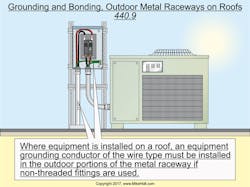
440.9 Grounding and Bonding. Where metal raceway is run exposed on a roof for airâconditioning and refrigeration equipment, an equipment grounding conductor of the wire type must be installed within the outdoor portions of metal raceways using non-threaded fittings (Fig. 15).
Analysis:
Electrical metallic tubing (EMT) is permitted to be used as an equipment grounding conductor (EGC) [250.118(4)]; research done by the Georgia Institute of Technology proves this wiring method serves this purpose. The concern is that the installation must have all fittings installed and tightened properly [110.3(B) and 250.4(A)(3)], and the raceway must not be subject to severe physical damage [358.12(1)]. Experience has shown that when EMT is installed on rooftops workers often step on it, thinking it’s impervious to damage. It isn’t. If EMT is used as the required circuit EGC and it comes apart due to being stepped on, we have a recipe for disaster. If the raceway becomes energized due to a ground fault, it remains energized. This rule also applies to any other metal raceway types that are installed using non-threaded fittings. Such a disaster has happened before, resulting in death, and unfortunately it will likely happen again. With this new rule in effect, it’s hoped that we can reduce this hazard for future generations.
Change No. 16: Section 517.13 (Grounding of Equipment in Patient Care Spaces)
The title of this Section was changed to match the rest of the Article. Some requirements for equipment grounding conductors (EGCs) in patient care spaces have been expanded while others are now reduced. Exception No. 2 of Sec. 517.13(B) was clarified, and isolated ground receptacles are no longer a black hole in this rule.
517.13 Grounding of Equipment in Patient Care Spaces
Wiring in patient care spaces must comply with (A) and (B):
Author’s Comments: Patient care spaces include patient rooms as well as examining rooms, therapy areas, treatment rooms, and some patient corridors. They don’t include business offices, corridors, lounges, day rooms, dining rooms, or similar areas not classified as patient care spaces [517.2].
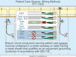
(A) Wiring Methods. Branch circuit conductors serving patient care spaces must be contained in a metal raceway or cable having a metal sheath that qualifies as an equipment grounding conductor in accordance with Sec. 250.118 (Fig. 16).
Author’s Comments: The metal sheath of traditional Type MC interlock cable isn’t identified as an equipment grounding conductor [250.118(10)(a)]; therefore, this wiring method isn’t permitted to be used for circuits in patient care spaces.
The metal sheath of Type AC cable is identified as an equipment grounding conductor in Sec. 250.118(8) because it contains an internal bonding strip that’s in direct contact with the metal sheath of the interlock cable.
The metal sheath of Type MCAP cable is identified
as an equipment grounding conductor in Sec. 250.118(10)(a) because it contains an internal bonding strip that’s in direct contact with the metal sheath of the interlock cable.
(B) Insulated Equipment Grounding Conductors and Insulated Bonding Jumpers.
(1) General. The following must be directly connected to an insulated copper equipment grounding conductor that has green insulation along its entire length and installed with the branch-circuit conductors in wiring methods as permitted in Sec. 517.13(A).
(1) The grounding contact of receptacles, other than isolated ground receptacles.
(2) Metal enclosures containing circuit conductors.
(3) Noncurrentâcarrying conductive surfaces of fixed electrical equipment likely to become energized that are subject to personal contact, operating at over 100V.
Exception No. 1: For other than isolated ground receptacles, an insulated equipment bonding jumper that directly connects to the equipment grounding conductor can connect the metal box and receptacle(s) to the equipment grounding conductor. Isolated ground receptacles must comply with the requirements contained in Sec. 517.16.
Exception No. 2: Metal faceplates for switches and receptacles can be connected to the equipment grounding conductor by the metal mounting screws that secure the faceplate to a metal outlet box or metal mounting yoke of switches [404.9(B)] and receptacles [406.4(C)].
Exception No. 3: Luminaires located more than 7½ ft above the floor and switches located outside of the patient care vicinity are permitted to be connected to an equipment grounding return path complying with Sec. 517.13(A) or (B).
(2) Sizing. Where metal receptacle boxes are used, the connection between the receptacle grounding terminal and the metal box must be copper wire sized no smaller than 12 AWG. Where receptacles and fixed electrical equipment are provided with overcurrent protection rated over 20A, equipment and bonding jumpers must be sized in accordance with Sec. 250.122, based on the rating of the overcurrent protection device.
Analysis:
Metal Enclosures. In patient care spaces, we need two equipment grounding conductors: One must be metal cable armor or a raceway type complying with Sec. 517.13(A); the other must be of the wire type installed inside the permitted wiring method in accordance with 517.13(B). The rules for the wire-type equipment grounding conductor in 517.13(B) have been changed to add clarity. For example, in the previous version of the NEC, 517.13(B)(1)(2) required metal receptacle boxes to be connected to a wire-type
equipment grounding conductor, but was silent on other metal enclosures! Now any metal enclosure housing electrical equipment must be connected to the equipment grounding conductor.
Luminaires. Exception No. 2 to Sec. 517.13(B) is one of the most misunderstood and misapplied allowances in the Code. In previous editions, luminaires above 7 ft 6 in., as well as switches outside the patient vicinity, only needed to comply with 517.13(A) and didn’t need to satisfy 517.13(B). While that sounds great at first glance, it didn’t do what most people thought it did. In the 2014 NEC, after applying the exception, if you used a cable wiring method, you couldn’t use traditional Type MC cable. Inspectors across the country regularly find themselves in situations where they must require thousands of feet of Type MC cable above the ceiling of a patient care space to be removed. Each time, it’s due to a misunderstanding of the exceptions in this Section of the Code. The change to 517.13(B) Exception No. 2 will permit compliance by meeting the requirements of either 517.13(A) or (B). This means that typical MC cable can be used 7 ft, 6 in. above a patient care space.
Isolated Ground Receptacles. Isolated ground (IG) receptacles have long been a problem in this Section. How does a person satisfy these rules when using an IG receptacle? Up until now it was easy. You couldn’t use an IG receptacle and still satisfy the letter of this Section. Changes to the 2017 edition now remedy this problem by giving specific provisions for IG receptacles, but remember that their use is still quite limited by the requirements in Sec. 517.16.
Change No. 17: Section 555.1 (Scope)
The title of this Article, its scope, and many of its provisions were changed to include residential installations.
Article 555 covers the installation of wiring and equipment for fixed or floating piers, wharfs, docks, and other areas in marinas, boatyards, boat basins, boathouses, and similar occupancies, including one-, two-, and multifamily dwellings, and residential condominiums (Fig. 17).
Author’s Comments: GFCI protection is required for outdoor 15A and 20A, 125V receptacles [210.8].
Analysis:
It’s not an exaggeration to say that marinas and boatyards are becoming a major problem in the electrical industry. People are swimming in these locations, and they’re being electrocuted or drowning due to electric shock and the subsequent inability to swim. This phenomenon is known as electric shock drowning (ESD). A quick search on the Internet will find dozens of such stories.
Over the past few Code cycles, we’ve seen added safety requirements for these locations as the risk of electrical hazards has become more and more apparent. While these changes certainly help, they were always inherently limited by the scope of this Article, because single-family dwelling installations were entirely exempt. One could even argue that townhouses and 2-family dwellings, as well as apartment facilities, weren’t covered. This is no longer the case, as the scope has been expanded to include dwellings and end any argument whatsoever about the applicability to residential installations.
Change No. 18: Section 555.3 (Ground-Fault Protection)
The trip setting of the ground-fault protection device required in this Section was reduced.
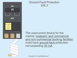
The overcurrent protection device(s) that supply marinas, boatyards, and commercial and noncommercial docking facilities must have ground-fault protection not exceeding 30 mA (Fig. 18).
Analysis:
This requirement was added to the NEC a few Code cycles ago to address the startling number of electrical injuries and deaths that have occurred around marinas and boatyards. The rule requires ground-fault protection but not at personnel protection levels (4mA to 6mA). Previous editions of the rule set the protection value at 100mA, and while that seems incredibly high, it would probably still prevent quite a few accidents. That value was lowered to 30mA in the 2017 edition of the NEC as a result of recommendations by the Fire Protection Research Foundation in their report titled Assessment of Hazardous Voltage/Current in Marinas, Boatyards and Floating Buildings. There can be no argument whatsoever that this change will increase safety, and with the number of tragedies we’re seeing, it’s a welcome one. Further changes were made to the language in this rule to clarify that it applies to all facilities within the scope of the Article, including residential facilities.
Change No. 19: Section 555.24 (Electric Shock Hazard Signage)
A new Section requires a warning sign at boat docks or marinas.
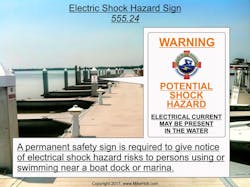
555.24 Electric Shock Hazard Signage. A permanent safety sign is required to give notice of electrical shock hazard risks to persons using or swimming near a boat dock or marina, and safety signs must meet all of the following requirements (Fig. 19):
(1) The sign must warn of the hazards using effective words, colors, or symbols or combination in accordance with 110.21(B)(1) and be of sufficient durability to withstand the environment.
(2) The signs must be clearly visible from all approaches to a marina or boatyard facility.
(3) The signs must state:
WARNING — POTENTIAL SHOCK HAZARD — ELECTRICAL CURRENTS MAY BE PRESENT IN THE WATER
Analysis:
This new requirement is intended to save lives. It comes from a recommendation made by the Fire Protection Research Foundation in their report titled “Assessment of Hazardous Voltage/Current in Marinas, Boatyards and Floating Buildings” to warn people of electrical hazards in the water. While this signage does nothing to remove the electrical hazard, it does the next best thing by letting people know to stay out of the water when near boat docks or marinas.
Change No. 20: Section 590.6 (Ground-Fault Protection for Personnel)
New allowances permit listed cord sets or devices with GFCI protection in addition to the required GFCI protection for personnel, and now permit “special-purpose GFCIs” for receptacles.
(A) Receptacle Outlets. Ground-fault protection for personnel is required for temporary wiring used for construction, remodeling, maintenance, repair, or demolition of buildings, structures, or equipment.
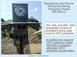
(1) Receptacles Not Part of Permanent Wiring. 15A, 20A, and 30A, 125V and 125/250V, single-phase receptacles that aren’t part of the permanent wiring of the building or structure and that are in use by personnel must be GFCI protected. In addition to the required GFCI protection for personnel, listed cord sets or devices incorporating listed ground-fault circuit-interrupter protection for personnel identified for portable use are permitted (Fig. 20).
(2) Receptacle Outlets Existing or Installed as Permanent Wiring. GFCI protection is required for all 15A, 20A, and 30A, 125V receptacle outlets that are installed or existing as part of the permanent wiring of the building.
Listed flexible cord sets or devices that incorporate listed GFCI protection can be used to meet this requirement.
(3) Portable Generators. GFCI protection is required for all 15A, 20A, and 30A, 125/250V receptacles that are part of a portable generator rated not greater than 15kW.
(B) Other Receptacles. For temporary wiring installations, receptacles, other than those covered by Sec. 590.6(A)(1) through (A)(3) that supply temporary power used by personnel during construction, remodeling, maintenance, repair, or demolition of buildings, structures, equipment, or similar activities must be GFCI protected in accordance with Sec. 590.6(B)(1), (B)(2), or utilize the assured equipment
grounding conductor program in accordance with Sec. 590.6(B)(3).
(1) GFCI Protection. Ground-fault circuit-interrupter (GFCI) protection for personnel.
(2) SPGFCI Protection. Special purpose ground-fault circuit-interrupter protection for personnel.
Analysis:
GFCI protection has been required for receptacles other than those rated 15A, 20A, and 30A, 125V for quite some time. The only alternative to this has been the assured equipment grounding conductor program. New to the 2017 NEC is an allowance for “special-purpose GFCIs.” Special-purpose GFCIs are classified as Class C, D, or E, and they trip at 20mA instead of the 6mA of a Class A GFCI. Although special-purpose GFCIs trip at a higher current value than Class A GFCIs, they still provide protection due to the speed at which they open the circuit during a ground fault. Remember that the severity of an electric shock is dependent on two things: the amount of current and the length of time the victim is exposed to it. For example, 75mA for 0.50 seconds will typically send the victim into ventricular fibrillation; 20mA for a very short period of time is still considered safe.
Change No. 21: Section 680.25 (Feeders)
The wiring methods for feeders supplying pools and similar installations were changed into a reasonable requirement.
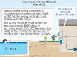
(A) Wiring Methods. Where feeder wiring is installed in corrosive environments as described in Sec. 680.14, the wiring methods must comply with 680.14(B) or be liquidtight flexible nonmetallic conduit. The wiring methods must contain an insulated copper equipment grounding conductor sized in accordance with Sec. 250.122, based on the rating of the overcurrent protection device, but in no case can it be smaller than 12 AWG (Fig. 21).
In noncorrosive environments, any Chapter 3 wiring method is permitted.
Analysis:
Previous editions of this requirement were so unrealistically restrictive that many inspectors simply ignored them. The requirements were vague as to their applicability and were the subject of many debates. If a person wanted to add a pool to an existing house, it often required remodeling a significant portion of the electrical system, assuming the environment was corrosive, but it did absolutely nothing to increase the safety of the overall installation. This Code section implied that adding a pool made the wiring inside the house unsafe. The NEC now contains specific requirements for feeders installed in corrosive environments and allows for any Chapter 3 wiring method in environments where corrosion isn’t a problem — what a welcome change.
Change No. 22: Section 680.74 (Equipotential Bonding)
The rules for bonding hydromassage tubs have been reorganized and revised.
(A) General. The following parts must be bonded together.
(1) Metal fittings within or attached to the hydromassage tub structure that are in contact with the circulating water.
(2) Metal parts of electrical equipment associated with the hydromassage tub water circulating system, including pump and blower motors.
(3) Metal-sheathed cables, metal raceways, and metal piping within 5 ft of the inside walls of the hydromassage tub and not separated from the tub area by a permanent barrier.
(4) Exposed metal surfaces within 5 ft of the inside walls of the hydromassage tub and not separated from the tub by a permanent barrier.
(5) Electrical devices not associated with the hydromassage tubs located within 5 ft from the hydromassage tub.
Exception No. 1: Small conductive surfaces not likely to become energized, such as air and water jets, supply valve assemblies, and drain fittings not connected to metallic piping, and towel bars, mirror frames, and similar nonelectrical equipment not connected to metal framing aren’t required to be bonded.
Exception No. 2: Double-insulated motors and blowers aren’t required to be bonded.
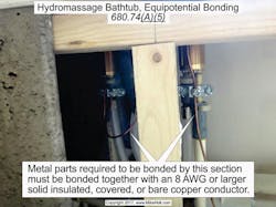
(B) Bonding Conductor. Metal parts required to be bonded by 680.74(A) must be bonded together using a solid copper conductor not smaller than 8 AWG (Fig. 22). The bonding jumper isn’t required to be extended or attached to any remote panelboard, service equipment, or any electrode. A bonding jumper long enough to terminate on a replacement nondouble-insulated pump or blower motor must be provided and it must terminate to the equipment grounding conductor of the branch circuit of the motor when a double-insulated circulating pump or blower motor is used.
Analysis:
There are a few Sections in the Code that you know are going to be revised every three years like clockwork: One is Sec. 110.16, and the other is Sec. 680.74. Bonding a hydromassage tub is still a bit of a mystery. There’ve been no documented incidents of electrocution or even injury that I’ve been able to find, yet we’re required to install an 8 AWG conductor in its vicinity, even when a double-insulated motor is installed.
New to this edition of the NEC, we find ourselves needing to bond objects within 5 ft of the tub, unless they’re small and unlikely to become energized. Several years ago, it was very common to find fireplaces installed at the foot of a hydromassage tub. With these new requirements, the fireplace will need to be bonded.
Change No. 23: Section 695.15 (Surge Protection)
Fire pump controllers must now have surge protection.
695.15 Surge Protection. A listed surge protection device [Art. 285] must be installed in or on the fire pump controller.
Analysis:
Few people argue the advantages of having surge protection. In a commercial building, the computers probably all have surge protection, but the fire pump controller doesn’t. A study was conducted, commissioned by the NFPA Fire Protection Research Foundation, and it concluded that 12% of the fire pumps tested had damage due to surges. Surges can damage motor windings, which shortens the life of motors. Controls are at even greater risk for damage from surges. It’s not prudent if a fire pump has to operate during a fire at full capacity and can’t because of unnoticed damage. This requirement is pretty easy to justify from a safety perspective.
Change No. 24: Sections 700.3 and 701.3 (Tests and Maintenance)
The equipment that might require maintenance is no longer limited to just batteries.
700.3 Tests and Maintenance
(A) Conduct or Witness Test. To ensure that the emergency power system meets or exceeds the original installation specifications, the authority having jurisdiction must conduct or witness an acceptance test of the emergency power system upon completion.
(B) Periodic Testing. Emergency power systems must be periodically tested to ensure that adequate maintenance has been performed and that the systems are in proper operating condition.
Author’s Comment: Running the emergency power system under load is often considered an acceptable method of operational testing.
(C) Maintenance. Emergency system equipment must be maintained in accordance with manufacturer instructions and industry standards.
(D) Written Record. A written record must be kept of all required tests [700.4(A) and (B)] and maintenance [700.4(C)].
Author’s Comment: The NEC doesn’t specify the required record retention period.
701.3 Tests and Maintenance
(A) Conduct or Witness Test. To ensure that the legally required standby system meets or exceeds the original installation specifications, the authority having jurisdiction must conduct or witness an acceptance test of the legally required system upon completion of the installation.
(B) Periodic Testing. Legally required standby systems must be periodically tested to ensure that adequate maintenance has been performed and that the systems are in proper operating condition.
Author’s Comment: Running the legally required standby system to power the loads of the facility is often considered an acceptable method of operational testing.
(C) Maintenance. Legally required standby system equipment must be maintained in accordance with manufacturer instructions and industry standards.
(D) Written Record. A written record must be kept of all required tests and maintenance [700.4(C)].
Author’s Comment: The NEC doesn’t specify the required record retention period.
Analysis:
Previous editions of the Code required batteries to be maintained, whether they were for starting a generator, turning on an exit sign, or any other purpose. These two Sections of the Code have been expanded to include other emergency power equipment and legally required power equipment requiring maintenance like generators, transfer switches, and panels.
Change No. 25: Sections 700.5, 701.5 and 702.5 (Transfer Equipment)
Transfer equipment must now be marked by the installer to indicate its short-circuit current rating.
700.5 Transfer Equipment
(A) General. Transfer equipment must be automatic and be installed to prevent the inadvertent interconnection of normal and alternate sources of supply.
(C) Automatic Transfer Switches. Automatic transfer switches must be listed for emergency power system use.
(D) Use. Transfer equipment must supply only emergency loads.
Author’s Comment: Multiple transfer switches are required where a single generator is used to supply both emergency loads and other loads.
(E) Documentation. The shortâcircuit current rating of the transfer equipment must be field marked on the exterior of the transfer equipment.
701.5 Transfer Equipment
(A) General. Transfer equipment must be automatic and be installed to prevent the inadvertent interconnection of normal and alternate sources of supply.
Author’s Comment: Legally required standby systems and optional standby systems can be on the same transfer switch, but emergency power systems must have their own [700.6(D)].
(C) Automatic Transfer Switch. Automatic transfer switches must be listed for emergency use (Fig. 23).
(D) Documentation. The short-circuit current rating of the transfer equipment must be field marked on the exterior of the transfer equipment.
702.5 Transfer Equipment
Transfer equipment is required for all fixed or portable optional standby systems.
Exception: Temporary connection of a portable generator without transfer equipment is permitted where conditions of maintenance and supervision ensure that only qualified persons will service the installation, and where the normal supply is physically isolated by a lockable disconnect or by the disconnection of the normal supply conductors.
The shortâcircuit current rating of the transfer equipment must be field marked on the exterior of the transfer equipment.
Analysis:
Transfer equipment is required by UL 1008 to be marked with its short-circuit current rating. At first glance, this seems to be a rule with automatic compliance, but it does require some involvement from the installer. According to the Code Making Panel, transfer switches are typically marked with several different ratings that can vary based on the type(s) of overcurrent protection device(s) that are installed. If this is the case, the installer must determine which rating is applicable and indicate it on the equipment.
Section 701.5(D), like 700.5(E), was added to require the installer to indicate the short-circuit current rating of transfer equipment. UL 1008 already requires the equipment to be marked with its short-circuit current rating, but this rule still requires some involvement from the installer.
The change to Sec. 702.5 was made to be consistent with the changes made in 700.5 and 701.5.
These materials are provided to us by Mike Holt Enterprises in Leesburg, Fla. To view Code training materials offered by this company, visit www.mikeholt.com/code.
About the Author

Mike Holt
Mike Holt is the owner of Mike Holt Enterprises (www.MikeHolt.com), one of the largest electrical publishers in the United States. He earned a master's degree in the Business Administration Program (MBA) from the University of Miami. He earned his reputation as a National Electrical Code (NEC) expert by working his way up through the electrical trade. Formally a construction editor for two different trade publications, Mike started his career as an apprentice electrician and eventually became a master electrician, an electrical inspector, a contractor, and an educator. Mike has taught more than 1,000 classes on 30 different electrical-related subjects — ranging from alarm installations to exam preparation and voltage drop calculations. He continues to produce seminars, videos, books, and online training for the trade as well as contribute monthly Code content to EC&M magazine.
