Practically Speaking: When is Ampacity Not Really Ampacity?
The term “ampacity” is used hundreds of times throughout the Code and is defined in Art. 100 as “the maximum current, in amperes, that a conductor can carry continuously under the conditions of use without exceeding its temperature rating.” Based on this definition, I think it’s accurate to say the conditions of use would include any adjustments for current-carrying conductors or corrections for ambient temperature.
The conductor ampacities in Table 310.16 are based on not more than three current-carrying conductors and wiring installed in an 86°F ambient temperature. The adjustment factors in Table 310.15(C)(1) are applied when there are more than three current-carrying conductors, and the correction factors in Table 310.15(B)(1) are applied when the ambient temperature is other than 86°F. So, one would assume, anytime the Code requires us to calculate a minimum conductor ampacity, we should include the ambient temperature correction factors and current-carrying adjustment factors too. This is true for sizing conductors as specified in Secs. 240.21(B), 240.21(C), 334.80, 409.20, 424.4(B), 430.22, 430.24, 460.8(A), 630.11(A), and virtually every other time the Code establishes a minimum conductor ampacity.
This makes sense and aligns with the definition of “ampacity.” However, when applying the requirements to feeder conductors as specified in Sec. 215.2(A), definitions don’t seem to matter as much as the intent of the wording.
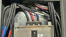
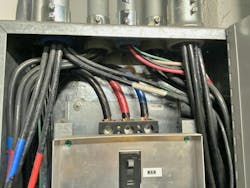
I would like to say thank you to instructor Jeremy Weed for the following example showing us why. In this scenario, the feeder has four current-carrying conductors and is installed in an ambient temperature of 125°F. The load includes 75A of noncontinuous load and 119A of continuous load. The copper THHN conductors are protected by a 225A breaker. For Sec. 215.2(A)(1), the intent is to size the conductor to not less than 125% of the continuous load, but excluding any corrections or adjustments. The intent here is to keep the conductor/equipment terminal connection from overheating.
For our example, (119A x 125%) + 75A = 223.75A minimum. The intent is for us to choose the wire directly from Table 310.16 to correlate with the equipment terminals, but without applying any corrections or adjustments. A 4/0 conductor in the 75°C column of Table 310.16 is rated for 230A and satisfies this requirement. This method, however, does not align with the literal definition of ampacity because the conditions of use for the example installation are different than those specified in Table 310.16. If we apply the definition of ampacity here — and include corrections for the 125°F ambient temperature and adjustments for four current-carrying conductors — the conductor will need an ampacity of 223.75A. That would require a 400kcmil THHN, which would have an ampacity of 231.04A under the specified conditions of use. (380A x .76 x .8 = 231.04A).
Which conductor size is correct? Well, as Jeremy pointed out, based on Example D3(a) in Annex D, the 4/0 THHN would apparently satisfy Sec. 215.2(A)(1). But there is another piece to this puzzle we must find before we choose our wire. Section 215.2(A)(2) requires the feeder conductors to have “an ampacity not less than the maximum load to be served after the application of any adjustment or correction factor in accordance with Sec. 310.14”. Why bother stating “after the application of any adjustment or correction factor” when the definition of ampacity already includes that? It seems a little redundant and unnecessary, but this is the clue we needed to explain that Sec. 215.2(A)(1)
should be calculated excluding any adjustments or corrections despite the seemingly incorrect usage of the term “ampacity” in Sec. 215.2(A)(1). The actual load is 194A (119A + 75A = 194A), and, for our example, the 400kcmil conductor had an ampacity of 231.04A and would satisfy both Sec. 215.2(A)(2) and Sec. 215.2(A)(1). The 4/0, however, would have an ampacity of only 139.84A (230A x .76 x .8 = 139.84A) and would not satisfy Sec. 215.2(A)(2).
Jeremy pointed out that a 350kcmil THHN would satisfy Sec. 215.2(A)(1)
if we ignore the true definition of ampacity and instead follow the intent rather than the literal wording, since it’s ampacity in the 75°C column of Table 310.16 is 310A. That 350kcmil THHN would also satisfy Sec. 215.2(A)(2), since its ampacity after applying corrections and adjustments would be 212.8A (350A x .76 x.8 = 212.8A).
Section 215.2(A) requires feeder conductors to have an ampacity no less than the greater of Sec. 215.2(A)(1) or Sec. 215.2(A)(2). This means both of these calculations must be done to choose the correct wire size. You will just need to decide how closely you want to adhere to the meaning of clearly defined terms and literal wording versus the intent of the words. In the case of Sec. 215.2(A), ampacity may not mean “ampacity” when it comes to sizing conductors for continuous loads. By the way, we could probably discuss the same issues in Sec. 210.19 for branch-circuit conductors and Sec. 230.42(A) for service entrance conductors, too.
About the Author

Russ LeBlanc
Owner
Russ started in the electrical trade as an apprentice in 1985. He worked his way up to become a Journeyman Electrician and then eventually became a Master Electrician and Licensed Construction Supervisor. In 1999 Russ become an Electrical Instructor for The Peterson School of Engineering in Massachusetts where he developed his passion for teaching, and quickly became Department Head of Electrical Instruction. Russ has taught thousands of apprentices, electricians, engineers, inspectors, and other electrical professionals during his career as an instructor. He continues to provide electrical professionals with Electrical Code seminars, Arc-Flash Awareness training seminars and educational material through his LeBlanc Consulting Services in North Reading, MA whose specialty is educating electricians. He has been an active member of the NFPA Electrical Section and has authored hundreds of National Electrical Code proposals and comments which have become Code rules to improve the safety for the electrical industry. Russ is also an IAEI certified Electrical Inspector.
Please visit www.russleblanc.net for more information.

