Interconnection Basics for Photovoltaic Systems
Photovoltaic (PV) installations in the United States are most commonly interconnected with electric utility systems as opposed to being set up as stand-alone or off-grid systems. The most common types of PV systems are the grid-direct variety — or those that do not use energy storage, namely batteries. These grid-direct systems have an inverter connected directly to the PV array on the DC side and are directly connected to the electric utility system on the AC side.
The inverters vary greatly in size and power ratings — from micro-inverters rated at around 200W and mounted underneath the modules to inverters rated in the MW range and connected to utility-scale PV power plants. For commercial and residential systems, the size of inverters varies greatly, but the fundamentals for grid interconnection are nearly identical. Let’s take a look at the 2011 NEC requirements and common industry practices for making the grid connection from a PV system. For more recent requirements in the Code, see 2014 NEC Changes.
To get started in the interconnection process, go to Art. 705, “Interconnected Electric Power Production Sources.” This section covers the two types of interconnections available to installers. One thing to note is, in 2011, the Code references for electric utility interconnection were moved from 690.64 to 705.12. The rules are nearly identical, and the move to 705.12 reflects the ability of other system types — not just PV — to interconnect and operate in parallel with the grid.
Line-side connection
Section 705.12(A) allows for interconnected power sources to connect to the supply side of the service disconnecting means and references 230.82(6) in this allowance. An addition was made in the 2011 edition of the Code stating, “the sum of the ratings of all overcurrent devices connected to the power production sources shall not exceed the rating of the service.” This allows us to connect a PV power source to the service conductors with an output less than or equal to the rating of the conductors.
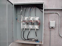
As far as clear and direct rules go for supply-side connections, that is the extent of the Code language, which has left many installers and authorities having jurisdiction (AHJs) to interpret the Code requirements for making these line-side connections (Photo 1). In the end, most have collected rules from Art. 230 to apply to these scenarios and allow for a safe method of interconnection. The term “line-side tap” is often used to describe the method for connecting a PV system to the service conductors. While this gives a good description and quick visual of the connection method, it often sends people to Sec. 240.21. The connection being made is not on the feeders, which is what 240.21 is covering; therefore, we cannot truly apply the requirements of this Code section to a grid-type interconnection.
The other common reaction to supply-side connection is to look at the requirements for service-disconnecting means. This has become commonplace in the PV industry. However, it should be noted that the PV system cannot be defined as a service. Therefore, the associated disconnect would technically not be a service disconnect. In reality, based on the way the Code covers these connections and the language it applies to the conductors used, we are effectively treating the connection as a service disconnect and need to follow the rules in Art. 230. This typically requires service-rated disconnects and overcurrent protective devices (OCPDs) at the point of interconnection.
One of the service-disconnect rules that comes up quite commonly for PV installations, especially in commercial installations, is 230.71, or the “six-handle” rule. Most electricians know you can’t have more than six sets of disconnects per service. One thing to pay close attention to is the language in the beginning of 230.71. Let’s review a few of the most pertinent parts of this section of the Code.
In 231.71(A), we learn that there shall not be more than six switches or circuit breakers (or combination of switches and circuit breakers) for each service permitted by 230.2 or for each set of service-entrance conductors allowed by 230.40 Exceptions 1, 3, 4, and 5. Let’s look at Exception 5 in more detail. It allows for multiple service-entrance conductor sets, specifically for PV systems by way of 230.82(6), to be connected to the service conductors ahead of the normal service-disconnecting means. Therefore, based on the allowances in 230.71(A), there can be as many as six disconnects for a PV system in addition to the six for traditional electric utility service disconnects.
This flies in the face of typical convention and general acceptance by many, including some AHJs. I have seen first-hand both scenarios: installations that use this method and have been accepted by the AHJ as well as systems where this was considered unacceptable, regardless of the language in the sections mentioned here. My suggestion to anyone wanting to apply this installation practice is to consult your AHJ ahead of time. This is a case where asking for forgiveness and fixing after the fact may end up costing you a lot of money and heartache later.
Load-side connection
For many commercial systems and most residential systems, a simple load-side connection generally proves to be the most effective way to connect an inverter to the electric utility system. Section 705.12(D) has seven relatively straightforward rules to apply in order to make this connection. These rules apply when you have multiple sources of power present in the distribution equipment, such as the electric utility feed and a PV array, and the distribution equipment is capable of supplying multiple branch circuits and/or feeders. This is true for nearly all residential and commercial main distribution panels that include a main OCPD.
Rule No. 1
When connecting the inverter(s) to the distribution equipment, each source interconnection needs a dedicated circuit breaker or fusible disconnecting means [705.12(D)(1)]. This means larger string inverters need a dedicated OCPD and disconnecting means. Typically, this is achieved with a circuit breaker. For micro-inverters, they are listed to be connected together, forming a branch circuit, and each branch circuit requires a dedicated OCPD and disconnect. You cannot take multiple inverter outputs or multiple mico-inverter branch circuits and place them in parallel before a dedicated OCPD.
Rule No. 2
This is commonly referred to as the “120% rule” [705.12(D)(2)]. The Code language allows the sum of the overcurrent devices supplying power to the bus bar or conductor to exceed the bus bar/conductor rating by 120%. I like to look at this in a very typical scenario. If you have a residential main distribution panel that is rated at 200A, this rule says the sum of the OCPDs supplying power can equal 240A (200A × 120% = 240A). In most cases, that 200A panel will be protected by a 200A main breaker. This leaves you, the solar installer, with a maximum of 40A (240A – 200A) worth of OCPDs to connect your PV system.
It is worth noting that 120% value is based off the rating of the bus bar or conductor. So you will want to take the time to look at the listing label and confirm the bus bar rating to determine the maximum PV OCPD rating you can interconnect. For example, a relatively new residential distribution panel is available with 225A bus bars and protected by a 200A main breaker. This leaves you with room for as much as 70A of PV OCPDs, if you so desire: 225A × 120% = 270A, 270A – 200A = 70A.
For those installing battery-based PV systems, make sure you understand the exception listed in 705.12(D)(2). Battery-based inverters operate differently than their grid-direct counterparts, and the 2011 Code recognizes that in this section. In these cases, you can use 125% of the electric utility-interactive current rating of the inverter, not the rating of the OCPD connecting in the distribution equipment, to determine the ampacity of the second supply to check the 120% calculation. This is to reflect that these inverters can pass a higher amount of current from the grid to the loads than they can send back into the grid. Ultimately, this feature requires a larger OCPD to avoid nuisance tripping and would severely restrict the size of inverter that could make a load-side connection and meet this section.
Rule No. 3
Simply stated, the interconnection point needs to be on the line side of all ground fault protection equipment [705.12(D)(3)]. This means if your main OCPD has integral ground fault protection (GFP), common in larger commercial services, the interconnection needs to move to the line side. As with many rules, there is an exception. If there is proper GFP for equipment from all ground fault current sources — and the GFP equipment is identified and listed for backfeed — you can make the load-side connection. I have heard of, but never seen directly, GFP manufacturers providing documentation that their equipment is listed for backfeed.
Rule No. 4
The equipment you are connecting multiple power sources to needs to be labeled for the presence of multiple power sources [705.12(D)(4)]. This section doesn’t give specific language for this marking, but typically a label indicating the presence of both PV and electric utility power sources on the front cover is acceptable.
Rule No. 5
The circuit breakers you connect to need to be suitable for backfeeding [705.12(D)(5)]. Typically, this isn’t information the circuit breakers have explicitly stamped on their sides. An informational note helps explain that breakers do have the information on them though. If a breaker is stamped with “line” on one end and “load” on the other, then it is not suitable for backfeed. The lack of such line and load designations indicates the breakers are appropriate for backfeeding.
Rule No. 6
The circuit breakers that are used for fastening do not require a hold-down kit as a breaker connected to a standard engine generator would [705.12(D)(6)]. Because the inverter will stop producing power as soon as the electric utility power is removed, a circuit breaker that is removed from the panelboard will not present a shock hazard.
Rule No. 7
This last section dictates the location of the inverter’s OCPD in relation to the input breaker from the electric utility [705.12(D)(7)]. If the sum of the
OCPDs, utility plus inverter(s), is greater than the bus bar rating, the inverter OCPD must be located at the opposite end of the bus bar from the source OCPD. By placing them at opposite ends, the bus bar will never see current values that exceed its ratings, as the current from both sources will be flowing from the ends toward the center and never add to one another. If both breakers were located at one end, the currents could potentially be additive as the current flowed in the direction of the loads.
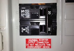
In addition to the location, a label is required for this scenario. The label language is called out in the Code and informs users of the breaker’s purpose and warns against moving the breaker in the future (Photo 2). If the sum of the OCPDs (utility plus inverter) doesn’t exceed the bus bar rating, then the location of the inverter OCPD is not limited by this section, nor is the label required.
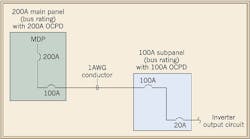
For PV systems where the inverter is connected to a subpanel instead of the main panel, this section of the Code has a provision for the calculations and OCPD values used. In that case, you are to use the rating of the OCPD(s) connected directly to the inverter(s) for the calculations of all bus bars and conductors. For example, consider a 20A PV breaker in a 100A-rated subpanel that is protected by a 100A breaker located in a 200A-rated main distribution panel that has a 200A OCPD (Figure). The first connection would be acceptable per 705.12(D)(2) because the 20A breaker plus the 100A breaker does not exceed 120% of the subpanel (100A + 20A = 120A). The 20A PV breaker would need to be placed at the opposite end from the electric utility feed and labeled appropriately.
When considering the connection in the 200A panel, you only need to consider the input from the 20A PV breaker, not the 100A subpanel breaker. In addition, the conductor from the main to the sub needs to have 100A of ampacity to pass the 705.12(D)(2) test. And because the sum of the OCPDs supplying power to the main panel would be 200A plus 20A and exceed the 200A bus bar rating, the 100A subpanel breaker should be placed at the opposite end of the panel from the 200A OCPD and be labeled as per 705.12(D)(7).
Bringing it all together
When you are first making these connections, take the time to review 705.12. As you become more comfortable and proficient in applying these rules, you will no longer find this portion of the Code to be confusing.
Mayfield is a principal with Renewable Energy Associates, Corvallis, Ore. He can be reached at [email protected].
SIDEBAR: 2014 NEC Changes
In the 2014 version of Code, you will see substantial additions to Sec. 705.12(D), with the majority of them in (D)(2). These additions add clarity to the different scenarios that occur when making a load-side connection. The first two subsections add language and rules for making the inverter output connection on feeders. This has been a common practice for some installers in the past. With these very explicit rules, the requirements are much better defined.
The third subsection to 705.12(D)(2) relates to inverter output connections made on bus bars. The new Code language lays out four different scenarios to account for the most common types of installation. These new rules allow contractors a bit more flexibility in the methods used to make interconnections on bus bars.
This section retains the 120% rule most installers are accustomed to. In addition, there is language that better defines the use of AC combiner panels for multiple inverter installations. In this version of the Code, 705.12(D)(2)(3)(c) allows multiple source and load OCPDs on the same panelboard, provided the sum of the OCPDs do not exceed the panelboard rating. This should be helpful as there have been multiple interpretations of this rule under previous Code cycles. Finally, there is also a new rule to address installing inverter output circuits on center-fed panelboards, which have been problematic in the past.


