Motors can be wired delta or wye. Which arrangement do you choose, and how do you do it? For purposes of making the connection, it doesn’t matter to the installer if the motor is delta-wound or wye-wound. The delta or wye connection is about the desired motor starting arrangement, not how the motor is wound.
Ideally, you will be connecting motors per an installation drawing. In that case, it’s a matter of correctly identifying the motor leads by number and connecting them per the drawing. Don’t try to “wing it” when replacing a motor, working with OEM equipment, or installing a motor when such drawings have been provided. But there’s a catch. We’ll get to that in a moment.
What if you don’t have drawings? What if the customer (the production department if you’re in maintenance) just wants a motor installed and the wiring is up to you? Your first task is to identify how many leads the motor has.
Typically, the motor will be a 6-lead or 9-lead motor. Motors with six leads are nearly always single-voltage motors. Such motors might be dual-winding motors, in which case you can wire them for a part winding start. You can connect them for a delta start or a wye start.
If it’s a three-phase, six lead motor, how do you get the wye start? Connect motor lead 1 to L1 (typically black), motor lead 2 to L2 (typically red), and motor lead 3 to L3 (typically blue). Connect the other motor leads (4, 5, and 6) together.
To get the delta start for a six lead motor, don’t connect 4, 5, and 6 together. Instead, connect motor lead 1 and 6 to L1 (typically black), motor lead 2 and 4 to L2 (typically red), and motor lead 3 and 5 to L3 (typically blue).
Three-phase motors with 9 leads are nearly always dual-voltage motors. Connecting these is a bit more complicated, and mistakes are actually common. Typically, these motors don’t permit a wye start with delta run; you can usually wire them only for a delta start. But there are exceptions (IEC motors, for example).
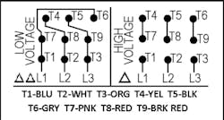
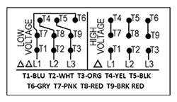
For the wye start, dual voltage nine lead motor on the lower voltage, connect 1 and 7 to L1, 2 and 8 to L2, and 3 and 9 to L3. Connect the remaining leads (4, 5, and 6) together. For the higher voltage, connect 1 to L1, 2 to L2, and 3 to L3. Connect 4 to 7, 5 to 8, and 6 to 9.
For the delta start, dual voltage nine lead motor on the lower voltage, connect 1, 6, and 7 to L1. Connect 2, 4, and 8 to L2. Connect 3, 5, and 9 to L3. For the higher voltage, connect 1 to L1, 2 to L2, and 3 to L3. Connect 4 to 7, 5 to 8, and 6 to 9.
To avoid confusion obtain a pocket motor wiring guide and refer to it while performing the work. We mentioned a catch, earlier. With these and other motor wiring variations possible, it’s easy to make a mistake. That drawing we said to follow could be wrong. Before you connect any wires, check the drawing carefully. That’s another reason to have that pocket motor wiring guide.
Before you actually make any bolted connections, verify the correct rotation using a rotation tester.
Also make sure you connect the “ground” wire to the “grounding” terminal of the motor. Note that this must be the power supply ground conductor, not a wire leading to a ground rod nearby.
About the Author

Mark Lamendola
Mark is an expert in maintenance management, having racked up an impressive track record during his time working in the field. He also has extensive knowledge of, and practical expertise with, the National Electrical Code (NEC). Through his consulting business, he provides articles and training materials on electrical topics, specializing in making difficult subjects easy to understand and focusing on the practical aspects of electrical work.
Prior to starting his own business, Mark served as the Technical Editor on EC&M for six years, worked three years in nuclear maintenance, six years as a contract project engineer/project manager, three years as a systems engineer, and three years in plant maintenance management.
Mark earned an AAS degree from Rock Valley College, a BSEET from Columbia Pacific University, and an MBA from Lake Erie College. He’s also completed several related certifications over the years and even was formerly licensed as a Master Electrician. He is a Senior Member of the IEEE and past Chairman of the Kansas City Chapters of both the IEEE and the IEEE Computer Society. Mark also served as the program director for, a board member of, and webmaster of, the Midwest Chapter of the 7x24 Exchange. He has also held memberships with the following organizations: NETA, NFPA, International Association of Webmasters, and Institute of Certified Professional Managers.

