Solving Critical Generator Problems with Neutral Grounding Resistors
A requirement for every hospital, emergency power generators must be operational in 10 seconds or less when electric utility power is lost. If a backup generator fails, the lives of hospital patients are most certainly at risk. Proper grounding is essential to the generator’s ability to function, but this important detail can be overlooked if not carefully evaluated.
Several challenges come with preparing a critical facility for an emergency electrical situation. When diesel generators are activated, the voltage, amperage, and synchronization among them must be exact. Without a firm grounding scheme, these parameters can cause an electrical fault, resulting in costly physical damage. This is precisely what happened during a recent project RMF Engineering worked on.
Initial challenges
In 2010, RMF was tasked with designing a generator system to serve a large hospital building to be constructed on a medical campus — 2MW diesel generators were an integral part of this design and needed to be incorporated into an existing 2MW generator that was being relocated to a new electric utility enclosure adjacent to the construction site. A new 1,200A, 5kV paralleling switchgear arrangement incorporated two separate electric utility feeder breakers and distributed emergency power to 5kV mechanical equipment and 480V emergency switchgear.
Required testing was performed on the generators, paralleling switchgear, and breakers after normal and emergency systems had been commissioned by a third-party commissioning agent. By the end of 2015, commissioning was substantially complete, and final testing of the generators and the associated paralleling switchgear was still ongoing.
During the final phase of testing, problems began to occur. The electrical contractor tried multiple times to switch emergency power from Feeder “A” to Feeder “B” on the 5kV/480V emergency transformer. However, each time it did, breaker “B” tripped on an overcurrent. RMF’s electrical team was called in by the owner to provide guidance as to the cause of the tripping. In the interim, breaker settings were checked and adjusted to alleviate this issue.
The following day, RMF was on-site to look into the cause of an arrester failure. The surge arresters installed on the emergency transformer were found to have a rating of 3kV (2.55 MCOV), which was not suitable for RMF’s resistance grounded system. The correct rating for this system is 6kV (5.1 MCOV). Fortunately, the surge arresters in the adjacent medium-voltage switches that were feeding the transformer were rated correctly.
RMF, the general contractor, the electrical contractor, the transfer switch manufacturer, the 5kV paralleling switchgear manufacturer, and the 5kV/480V switchgear manufacturer met that morning to evaluate the events leading up to the arrester failure.
Identifying the causes
The paralleling switchgear manufacturer was on-site the day before the surge arrester failure, attempting to conduct a load bank test on the relocated emergency generator. They discovered an issue with the differential relay circuit. This wiring was corrected with the paralleling switchgear manufacturer, the third-party testing agency, and the electrical contractor present.
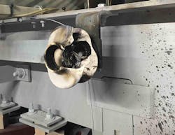
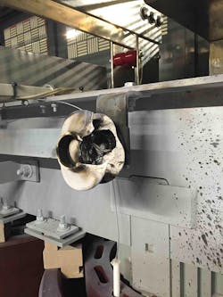
The next day, the paralleling switchgear manufacturer was attempting to again load bank test the relocated emergency generator, and the emergency generator breaker immediately tripped when closed to the 5kV paralleling switchgear bus. The third-party testing agency attempted to close the breaker several times, and it tripped each time on loss-of-phase detected by the differential relay. The breaker for one of the two new emergency generators tripped for the same reason. It was at this time that smoke was detected, and the failure was located in emergency switchgear “A.” A combination of the “A” and “C” surge arresters failing in emergency switchgear “A” caused the smoke (Photo 1).
After the meeting to discuss the failure, RMF, the paralleling switchgear manufacturer, and the electrical contractor performed the following tests:
• The “A” bus of the 5kV paralleling switchgear was isolated from bus “B,” and all “A” feeders were isolated from the bus. The “B” bus remained online to provide back-up operations to the adjacent occupied patient tower that was connected to the generators. One of the two new emergency generators was restarted and closed to the bus. Phase rotation and voltages were documented.
• The relocated emergency generator was then closed to the bus, again with the team noting rotation and voltage to match one of the two new emergency generators. The rotation and voltage was designed to match between generators.
• The “A” bus was tied back to the “B” bus, and both of the two new emergency generators were synchronized and closed to the bus. This ensured an operational system that reliably provided back-up power to the adjacent patient tower and emergency switchgear “B.”
• The “A” feeder adjacent to the patient tower was closed, bringing the system back to the pre-fault condition with the exception of emergency switchgear “A” (cleaning, testing, and installation of correct surge arresters was still ongoing).
• The team verified that the existing emergency switchgear “A” in the adjacent patient tower had the correct surge arresters installed. Switchgear “B” was incorrect, so the team directed the emergency switchgear manufacturer to change these out as well.
Even after identifying the incorrectly sized 3kV arresters, the team still needed to determine the cause of the arrester failure — improperly sized 3kV arresters should not have reached a high enough voltage to fail on their own.
The following day, additional personnel from RMF were on-site to monitor follow-up testing. The testing was performed, and the relocated emergency generator was started and isolated to the “A” side of the 5kV paralleling gear. Upon completion of testing, the system was returned to normal.
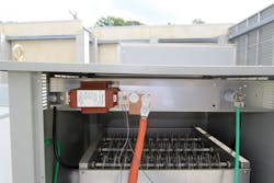
After the testing, RMF, the electrical contractor, and two test technicians from a third-party testing agency moved their focus to the relocated emergency generator to perform basic testing of the neutral grounding resistor (NGR). Testing revealed that the NGR was not grounded to building steel, and, as a result, the relocated emergency generator was not grounded. An electrical engineer from RMF advised the electrical contractor to ground the load-side of the NGR. Measurements were taken for new generators, and it was verified that these two NGRs were connected correctly and measured a nominal 8 ohms (Photo 2).
The importance of neutral grounding resistors
At the conclusion of testing, RMF found that the “A” and “C” phase surge arresters failed to ground during testing of the relocated emergency generator, most likely due to a voltage elevation during governor testing, which introduces transient voltages. This caused the voltage on “A” and “C” phases to become elevated, resulting in the failure of the surge arresters on those two phases. Since the NGR for the relocated emergency generator was not connected to ground, a ground fault current could not have been detected by the protective relay, which is why breakers didn’t operate sooner to protect the transformer.
After the corrections were made to the NGR at the relocated emergency generator — and the correctly sized surge arresters were installed on the 5kV/480V emergency transformer — final commissioning and testing was performed on all three generators. The three generators were synchronized, and load shedding was proven through a sequence provided by RMF. The relocated emergency generator sound, transient voltage, and back-pressure testing were performed and completed without issues.
The final test performed on the relocated emergency generator was the commissioning of the new 250-gallon day tank. At its previous location, the relocated emergency generator rested upon a 5,000-gallon belly tank. At the new location, the three generators were fed by underground tanks and required a separate day tank at each generator. During testing, the commissioning agent found no issues.
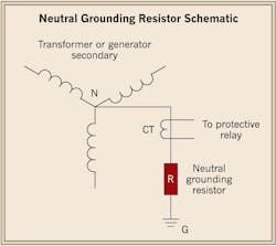
NGR systems (Figure) protect power transformers and generators from damaging fault currents by limiting neutral fault currents to a fixed level and setting protective devices to quickly clear the fault. Without a correctly sized and installed NGR, damage to equipment as noted above will occur.
Caputo is a licensed journeyman electrician, electrical construction inspector, and commissioning agent at RMF Engineering, Baltimore. He can be reached at [email protected].


