Harmonics of the 60 Hz power frequency has been around for a long time. It was observed on transmission systems in the early 1890s and was associated with voltage and current waveforms.
As equipment became more sophisticated — and with the proliferation of nonlinear loads — harmonics has become a pronounced problem on many power systems. In fact, according to some industry experts, nonlinear loads are approaching 75% to 90% of the loading on our nation's electric utility distribution systems in many areas.
Harmonics can be produced in a plant and/or may enter a plant from the electric utility power system because of other offending sources on the line feeding the plant. IEEE Standard 519 has tried to address this by defining responsibility for both the electric utility and the user. The major concern for the electric utility is the quality of the voltage while the industrial user is responsible for the distortion of the current.
With more electric utilities imposing higher penalties for poor power factor these days, industrials are applying more capacitors to their systems to correct this situation. Because this increased use of capacitors can magnify the harmonic currents on the system, the electric utilities can strengthen their position by applying restriction to the harmonic currents being injected into the system by the industrial customer.
Harmonic sources
There are many sources of harmonics in industrial power systems, all of which share a common characteristic: a nonlinear voltage-current operating relationship. A nonlinear load has a discontinuous current that does not correspond to the applied voltage waveform. Any device that alters the sinusoidal waveform of the voltage or current is a harmonic producer. This includes such common components as transformers. Transformer inrush currents contain significant levels of low-order harmonics, such as the 2nd, 3rd, 4th, etc. In addition, the transformer magnetizing currents will contain increased levels of the 3rd, 5th, and 7th order harmonics, when the applied voltage is higher than the rated voltage.
More significant harmonic sources come from applications of solid-state devices for equipment control. The term “solid-state” includes:
-
Diodes (simple rectifiers)
-
Transistors
-
SCR or thyristor devices used in various applications for the control or regulation of drives
-
Rectifier output controls
-
Frequency conversion (variable-speed drives)
-
Arc furnaces and arc welding equipment are also significant producers of harmonics.
Solid-state harmonic-producing equipment is typically described by its pulse number. This is often noted as a “p-pulse” type system. The pulse number “p” is the number of pulsations (cycles of ripple) of the DC voltage per cycle of the AC voltage, and can be determined by the simple formula:
h =(n × p)± 1
Where:
n = an integer: 1, 2, 3, …
p = pulse number
h = the characteristic harmonics
The 6-pulse and 12-pulse systems are most common. For a 6-pulse system:
h = (1×6)± 1 [5th and 7th harmonics]
h =(2×6)±1 [11th and 13th harmonics]
The theoretical amplitude of each harmonic is the reciprocal of its harmonic number. For example, the 5th harmonic current would be 20% of the fundamental frequency supplied current. Most harmonic-producing loads can be modeled as a source of harmonic currents.
Negative effects
Harmonics may cause interference and inefficiencies in power systems and equipment. Some of the potential problems include:
-
There may be interference with communication and auto tone control equipment.
-
Metering may not register properly.
-
Harmonic currents circulating in the power system increase copper losses and the heating of equipment, such as transformers and generators.
-
Generators can have additional problems with excessive harmonic voltage distortion, causing multiple zero crossings of the current waveform. This can cause interference and operation instability.
-
Breaker and fuse operations may occur for no apparent reason.
Frequently, the first indication of significant levels of harmonics is associated with power factor correction capacitors. This could include capacitor failures (possibly ruptures) and capacitor fuse failures.
Capacitor issues
Capacitors are static or linear components, and they do not generate harmonics. However, they will interact with the electrical system source inductance and may create a parallel resonance condition at a troublesome harmonic. See Fig. 1 (click here to see Fig. 1) for a simple typical one-line diagram.
A simplified circuit model is shown in Fig. 2 (click here to see Fig. 2). Motors have high inductive impedance compared to the source impedance; therefore, we will ignore them in our circuit.
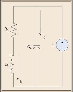
Combining transformer and electric utility source impedances is shown as RS and LS in Fig. 3. The shunt capacitance of the power factor correction capacitors is represented as CS.
In Fig. 3, the model has been rearranged for harmonic analysis and to emphasize the parallel L-C configuration with a harmonic current source.
If the circuit is resonant at a frequency in which harmonic currents are being injected by the load, circulating currents (IL & IC) will be approximately equal in magnitude and can be many times greater than the harmonic source IH.
Voltages across LS and CS can become large. This increase in current IC may cause fuses to blow, or the resulting higher voltages across the capacitors may cause the capacitor to fail or possibly rupture.
System changes and problems
With harmonics in the system and the addition of capacitors to correct power factor issues, it's easy to appreciate why an electrical system may be operating fine and suddenly start to malfunction, causing serious harmonic issues after a change is made to the system. Three issues must exist before a harmonic resonance problem will manifest itself:
-
The system must have capacitors.
-
The system must have significant sources of harmonic currents.
-
The system must be resonant at or near one of the characteristic harmonics of a significant harmonic source.
With the addition of power factor correction capacitors, a troublesome parallel resonance can be created. This may be an isolated bank or another bank added to the system. If a bank is already on the system, adding more capacitors could move the parallel resonance to a lower troublesome harmonic. The parallel resonant harmonic (HR) for a system can be calculated from:
Where:
HR = resonant frequency as a multiple of the fundamental frequency.
MVASC = short circuit current at the point of study
MVARC = shunt capacitor rating at the point of study
If it is determined that parallel resonance near a characteristic harmonic will occur (such as the 5th or the 7th), then mitigation may be required. This is usually accomplished with “detuning” the parallel resonance with a harmonic filter/capacitor package.
For a 6-pulse harmonic source, the filter design typically includes a reactor placed in series with the capacitors such that they are tuned at a chosen harmonic (i.e., the 3.8th, 4.2nd , 4.7th, etc.).
Detuning banks can accomplish two effects:
-
Provide a low-impedance shunt path near the characteristic harmonic that will “trap” some of the harmonic current.
-
The parallel resonant frequency being detuned is moved to a frequency below the 4.7th harmonic — or whatever the detuning point is — and away from the troublesome 5th harmonic.
If other capacitors without detuning reactors are present, then a parallel resonant frequency above the 4.7th (if this is the detuning point) will be created. Depending on other circuit constants involved, the parallel resonance may occur near the 7th or higher characteristic harmonic and may require additional detuning at the 7th harmonic. In other cases, it may be required to design a filter to remove more than one troublesome harmonic.
As power systems become more complex, all possible combinations of operating conditions and capacitor step switching must be considered, including other buses upstream and/or downstream of the harmonic sources.
Summing it up
As with anything else, the more information you obtain, the better your chances are of having a properly working system. A harmonic study should be made prior to adding power factor correction capacitors to any power system known to have harmonics. A decision not to perform a study is an invitation to harmonic resonance problems. Costly mitigation, which initially could have been provided economically, may be required at a far greater expense and aggravation.
Ciurro is an electrical engineer with Qual-Tech Engineers, Houston, Pa. He can be reached at [email protected].