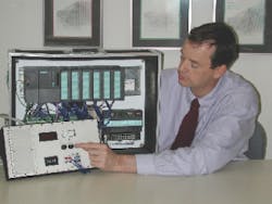
With integrated diagnostics and override functions, PLCs have become easier to use and much less expensive.
Before the automotive industry discovered the advantages of programmable logic controllers (PLCs), the process of modifying relay circuitry was a headache-inducing endeavor. In the past, annual car model changes forced plant engineers to constantly modify production equipment managed by relay circuitry. In some cases, the engineers had to scrap entire relay-controlled panels and replace them with completely redesigned systems. Now, PLCs allow engineers to implement numerous manufacturing changes with relative ease, which reduces changeover costs and downtime.
Prior to PLCs, contactor or relay controls solved many of these control tasks. This is often referred to as hard-wired control. Electricians had to design circuit diagrams, specify and install electrical components, and create wiring lists before wiring the components necessary to perform a specific task. Design errors would force the electrician to trace the wires to identify the problem and then reconnect the wires. A change in function or a system expansion required extensive component changes and rewiring.
PLCs are solid-state control devices that control, operate, and monitor various types of electrical systems found in commercial and industrial environments. PLCs consist of input modules or points, a central processing unit (CPU), and output modules or points. An input accepts a variety of digital or analog signals from various field sensors and converts them into logic signals the CPU can use. The CPU makes decisions and executes control instructions based on program instructions in memory. Output modules convert control instructions from the CPU into a digital or analog signal used to control various field devices, or actuators. A programming device is used to input the desired instructions. These instructions determine what the PLC will do for a specific input. An operator interface device displays process information and allows users to enter new control parameters.
Now, PLC software programming makes wiring changes between devices and relay contacts easier. Although hard wiring is still necessary for connecting field devices, it’s less intensive than before.
How do PLCs talk? PLCs communicate with each other through their own language. To understand the ideas and concepts of PLCs, it’s necessary to develop an understanding of the following terms.
Sensors. These devices convert a physical condition into an electrical signal for use by the PLC. Sensors connect to the PLC’s input connections. A pushbutton is one example of a sensor that connects to the PLC input. One of the electrical signals is sent from the pushbutton to the PLC indicating the condition (open/closed) of the pushbutton contacts.
Actuators. These units convert an electrical signal from the PLC into a physical condition. Actuators connect to the PLC output. A motor starter is an example of an actuator that is connected to the PLC output. Depending on the PLC output signal, the motor starter will either start or stop the motor.
Discrete inputs. Discrete, or digital, input is a signal that travels to the PLC and instructs it to execute a function. It’s either in an ON or OFF condition. Toggle switches, limit switches, proximity switches, pushbuttons, and contact closures are examples of discrete sensors that connect to a PLC. A discrete input may be referred to as a logic 1 or a logic high in the ON condition, and in the OFF condition it may be referred to as a logic 0 or a logic low.
Discrete outputs. These signals are either in an ON or OFF condition. Solenoids, contractor coils, and lamps are examples of actuator devices connected to discrete outputs. Discrete outputs may also be referred to as digital outputs.
Analog inputs. This form of input signal has a persistent condition. Typical analog inputs may vary from a continuous current flow of 0mA to 20mA, 4mA to 20mA, or 0V to 120V.
Analog output. This PLC-based output signal is continuous, and the output may be as simple as a 0VDC to 10VDC potential that drives an analog device. Signals that control devices indicating a desired speed, weight, or temperature are examples of analog outputs. You can also use the output signal on more complex applications, such as a current-to-pneumatic transducer for controlling an air-operated flow-control valve.
CPUs. These are the microprocessor systems that contain the system memory. They form the PLC decision-making unit. The CPU monitors the inputs and makes decisions based on instructions held in its program memory. The CPU performs relay, counting, timing, data comparison, and sequential operations.
What are the advantages of using PLCs? Because they’re smaller than hard-wired control and monitoring solutions, PLCs have become easier to use and much less expensive during past decades. They are more user-friendly, and they allow you to make changes much more quickly than with traditional control methods. PLCs come equipped with integrated diagnostics and override functions that allow you to immediately document application changes.
PLCs have come a long way from their use in automotive plant assembly lines. Now you can use them to control one operation or link them to several systems in a network configuration. From damping operations in a building HVAC system to controlling elevator recall functions and a facility’s fire alarm system, PLCs interface and control various operations of all or just some components of different systems—making them the standard among control devices.
McGee is a program manager in the training department of Siemens Energy & Automation Co. in Alpharetta, Ga.
