Proper planning and selection of surge suppression devices reduces downtime and purchase costs.
If you're ready to start looking for surge suppression components for your facility, you're one step closer to protecting your equipment. The next step — selecting what you need from all the surge suppression products on the market — can be much more difficult. For your dollar, do you want a lower clamp voltage, or do you want higher surge current capacity? Is a staged system cost-effective? For that matter, what do those terms even mean?
Let's start the analysis with a quick look at clamp voltage. This is the remnant or let-through voltage a surge protection device (SPD) passes to the load. This number can be confusing because it's not an absolute. Comparing clamp voltages without reference to the transient current is like comparing voltages of electrical systems in which you know only the kVA. You need to know the current for the number to be meaningful.
People often incorrectly assume that the term surge current capacity, or withstand, describes an SPD's level of protection. Instead, it's simply a rating of how much energy the SPD can withstand before failure. It largely depends on the size of the SPD — a larger one can withstand more energy. Keep in mind that the number of surges an SPD has to withstand will add up — regardless of whether it's one sizable event or several small ones. Specifying excess capacity may mean longer times between replacements — but it doesn't imply a higher degree of protection.
A closer look at clamp voltage.
SPDs attenuate, or suppress, a transient voltage event by shunting the current and clamping the voltage. Just as a water pipe can allow only so much water to flow, an SPD of a given size can conduct only so much energy. Thus, an SPD will clamp, or pass along, power at a higher voltage when currents are higher. In other words, as current changes, so does the clamping voltage. A metal oxide varistor (MOV) is a variable resistor. You must know the clamp voltage at the expected current levels at the equipment you're trying to protect.
As it travels into a facility, a transient changes forms — due to the impedance of the wiring and transformers — from an impulse-type event to a ringwave-type event. The natural inductance and resistance of the wiring infrastructure will create a typical ringwave event of 100 kHz. This is why you can use much smaller components at a wall outlet or surge plug strip than what you would use at a panelboard or service entrance. You see much lower surge currents at the downstream locations.
A Cat. C3, or service entrance event, has a maximum of 20,000V at 10,000A (high exposure). As we move into the building, the event lessens to Cat. B3 — a maximum of 6,000V at 500A (100 kHz ringwave). At the wall outlet, the value is 6,000V at 200A (100 kHz ringwave).
Don't let clamp voltage numbers fool you — you must match this specification to the load. ANSI/IEEE C62.41 lists and describes typical levels of transient current in today's facilities. What clamp voltage is acceptable? The Computer Business Equipment Manufacturers Association (CBEMA) has developed a standard of voltages required for stable operation of typical electronic equipment known as the CBEMA curve. From this curve, we know most modern electronic equipment can withstand a transient 20-µsec in duration, if that transient is five times greater than the nominal voltage. This is about a 848V peak on a 120V system:
120V×1.414×5=848V
For 277V equipment, the value would be higher:
277V×1.414×5=1,958V
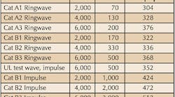
The typical 150V MOV will turn on at 205V peak (at a test current of 1mA) and will clamp at the levels shown in the Table. At lower surge currents, the MOV will clamp within the acceptable range. But as current rises, this clamp voltage increases.
A closer look at surge current capacity.
In general, the bigger the component, in this case MOV, the more surge current it can withstand — on both a one-time pulse basis and a repetitive basis. Fig. 1, below, shows common MOV sizes and single-impulse capacities.
Most manufacturers parallel multiple components with a derating factor to give them larger surge current capacities. You will often see product surge current ratings of 100kA to 200kA per mode — 10 to 20 times the typical event. This is a good engineering practice because SPDs can only take so much current before they significantly degrade or fail. NEMA standards consider an SPD to have failed when the clamp voltage is beyond 10% of the initial clamp voltage. As MOVs degrade, the clamp voltage decreases because less metal oxide substrate is available in the MOV. Eventually, a degraded MOV will try to clamp the normal sine wave. When it does, it will typically go into thermal runaway, short, and then fail in an open-state condition.
Developing a strategy.
With a better understanding of these two concepts, you're now better prepared to size components to match the equipment you're trying to protect. But this presents an obvious problem. How do you protect a 2,000A service entrance and 90A load with one device? You could simply protect at the point farthest upstream, thus protecting all the downstream equipment — just the way GFCIs, AFCIs, fuses, and breakers do. However, this method won't work because most transients come from inside a facility. Therefore, you must also protect your equipment from internal events.
You can't protect all of your equipment with a single SPD at the service entrance because it would be located upstream of transients generated inside the facility. To protect equipment from the main source of transients — those internal to the building — you must also provide SPDs at the appropriate distribution panels. Eliminating the SPD at the service entrance won't help you save much money, but you can cut down on costs by installing SPDs only at panels that supply power to equipment you want to protect. (Fig. 2)
-
One-stage system:
Ten 80 kA/mode SPDs with 10 panels, at $1,200 apiece, is $12,000.
-
Two-stage system:
One service entrance SPD, at $2,800; 10 panel SPDs, at $600 apiece, is $6,000. The total cost of such a system would be roughly $8,800 — a 27% cost savings over a one-stage system.
So not only does the two-stage system provide a lower clamp voltage and more reliability, but it also costs less.
Return on investment.
Because surge protection is considered a capital investment, cost analysis is essential. In addition to surge-related equipment repair costs, you must consider the lost revenue per hour of downtime, which is the total turnaround from shutdown to startup. If you examine each major piece of equipment you're trying to protect, these costs add up quickly. Be sure to include them in your capital request.
When bringing your surge protection proposal before the powers that be, the question will arise, How likely is a transient-induced failure? You need to assign a risk factor to those costs. Your financial people will use this to derive a multiplier on the downtime and repair costs, and your protection costs need to be less than their final number. Give them good information by comparing the CBEMA curves for your equipment to actual transient data for your facility, which you can get from a power monitor, if you haven't already been tracking failure causes in your maintenance logs. Once you've installed your two-stage surge suppression system, document the reduced costs. If you've planned your system and sized the components correctly, the results will be impressive.
Boyd is manager, industrial surge suppression products for Intermatic in Spring Grove, Ill.


