Riding Through Unstable Power Conditions With VFDs
You can't avoid power line disturbances altogether, but you do have access to options for mitigating voltage, current, and frequency deviations produced by the electric utility system. You can stabilize the overall voltage on the medium-voltage facility level or stabilize voltage deviations and their corresponding current and phase imbalances directly on the load or equipment side, which, in most cases, is low voltage.
A variable frequency drive (VFD) is one of the most versatile devices available for correcting power quality conditions. However, before you install one on your system you should fully understand how different power quality events affect these pulse-width modulated (PWM) devices.
Effects of power quality events. To determine the overall effect of a voltage, current, or frequency deviation on a drive, you need to know the distance to the fault, the impedance of the system upstream of the fault, the feeder impedance, and the transformer connections between the faulted system and the facility's electrical system bus.
Let's take a look at some power quality events and their effect on the operation of PWM, 6-pulse AC drives.
Voltage sags. Utility system faults are frequently asymmetrical, single line-to-ground faults that produce voltage sags. Voltage sags are a momentary decrease in rms voltage magnitude for typically one-half to 30 cycles, or 8 milliseconds to 0.5 second.
These sags are normally described by their magnitude and duration. But they also need to be understood in terms of the voltage imbalance, non-sinusoidal wave shapes, and phase angle shifts that accompany them.
AC drives can typically ride through a voltage sag because they store energy on their DC bus capacitors and make use of the energy stored in the load's inertia.
The drive's line voltage is monitored at the DC bus. Its control logic and fan power are taken from that bus. Therefore, the drive is independent of line voltage sag as long as the DC bus holds up. The DC bus will typically trip on undervoltage at an equivalent line voltage of 65% to 51% of nominal rated voltage.
On its own, the DC bus can deliver full power to a load for about one cycle, or 16 milliseconds, by allowing itself to decrease from its nominal voltage. As the bus voltage drops, the drive regulator adjusts the PWM pulse width to make up the reduced magnitude of the output voltage waveform of the inverter. Alternatively, the drive could allow the motor speed to decrease and use the energy stored in the inertia of the load to maintain bus voltage. Typically, more energy is stored in the load's inertia than the DC bus, making it possible to hold bus voltage for as long as 0.5 second to 5 seconds.
If the combination of the load's inertia and energy stored on the bus isn't enough to prevent the bus from tripping, the drive will use a programmable automatic restart function to recover. After the line condition has cleared, the drive will follow a programmed delay, find the motor speed, and accelerate the motor to set speed, resuming normal operation.
Phase imbalance. The phase imbalance associated with voltage sag is caused by the difference in the inductive reactance to resistance (X/R) ratios of the source and the faulted feed, and by the propagation of voltage sags due to single-phase faults through a transformer.
During normal operation, the input voltage to a drive is balanced and the diodes in the bridge rectifier are symmetrically forward-biased. A phase imbalance acts to lower the magnitude of one or more line-to-line voltages, reducing the peak voltage for one or more phases below the nominal capacitor voltage. This causes the rectifier diodes to not forward-bias. In this state, no energy flows from the AC mains to the capacitor. The capacitor will continue to discharge until it's hit by an input voltage peak that's high enough to forward-bias the diodes.
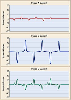
Since the capacitor has discharged more than its normal amount, the current drawn from the AC mains to recharge it to peak voltage will be quite high. In fact, the rms input current on some phases might exceed 200% of normal rating, and the associated peak current drawn in the high-current phase may be as much as four times the normal current (Fig. 1 on page 26). Under these conditions, an AC drive will often trip on overcurrent because the line current was too high or on undervoltage because the DC bus dropped below some threshold.
You'll see similar effects when single-phase loads are unevenly distributed on a 3-phase power system. The solution is to balance these loads more evenly across all three phases or install an AC line reactor at the AC drive that's experiencing problems. You should size the reactor to carry the drive's full load current, and it should have an impedance rating from 2% to 6%.
Single-phase input operation of drives for a short duration is usually not a concern. But if it's continuous, you'll need to derate the drive or size it by a factor of two or more times the actual power requirement. This is because single-phase current is 1.87 times the 3-phase current for the same power.
Voltage swell or overvoltage. Voltage-source PWM drives use a DC capacitor to smooth the rectified line voltage and act as an energy source for the inverter section of the drive. Line voltage to the drive is monitored at the DC capacitor or bus. Overvoltage trip points are normally set at 130% to 135% of nominal-rated voltage. An overvoltage trip inhibits drive operation but doesn't remove the drive from the line. And by regulating the motor voltage via pulse-width modulation, you can program the automatic restart function of the drive to recover from an overvoltage trip once the normal line condition is restored.
Frequency changes and operation on a generator. AC drives have a wide fundamental line frequency range of 47 Hz to 63 Hz. The rate of change should be less than 10 Hz/sec.
As shown in Fig. 2, the frequency delivered by a generator is related directly to its speed. As the generator is loaded, its speed and delivered frequency may drop.
Voltage transients. Capacitor switching is a common event on most electric utility systems. Utilities apply shunt capacitors on transmission systems, distribution feeders, and at substations. They adjust the line voltage for differences between daytime and nighttime loading and may be switched on a daily basis. Energizing these capacitors causes a transient voltage between the capacitor and the power system inductance.
Voltage transients are also caused by line switching of heavy loads, switching power factor correction capacitors, welding equipment, clearing line short-circuit faults, and lightning strikes.
Voltage transients are sudden, one-shot, sub-cycle voltage disturbances of tens to hundreds of microseconds in duration and could be over 1kV. You can purchase drives that have considerable built-in transient energy absorption capability.
Effects of system configuration and equipment. Certain pieces of equipment on your system and how they're ultimately connected can also affect the performance of your VFDs.
Wye-delta transformers. Transformer connections have an interesting effect on the ultimate line voltage at the load during an asymmetric fault. Most AC drives are fed from a 3-wire delivery without a neutral. As a result, the input rectifier stage only sees line-to-line voltages. At the fault location, a single-line-to-ground fault will yield a phase-to-neutral voltage of zero on one phase (top waveform, Fig. 3), but the other two phases are essentially unaffected.
If a wye-delta transformer is between the fault and load, two of the phase voltages on the delta side affected by the fault will fall to zero, but none of the line-to-line voltages will be affected. The drive will see a voltage sag on two of the line voltages (bottom waveform, Fig. 3). Similarly, a line-to-line fault will cause phase shifting and can cause a zero-voltage condition on a transformer's secondary.
Most AC drives require about 4% more AC input voltage than their maximum output voltage. For example, 460V output requires 480V input. This is due to residual zeros in the output waveform. Continuous low-line conditions may prevent the drive from delivering full output voltage.
As a point of fact, some drives can actually output 3% more voltage than the drive input in a certain mode, so with a 480V input the drive will output 495V.
Line impedance.The effect of electric utility impedance on the operation of a drive is a function of how stiff or soft the line is. Nominally (percent impedance is 1%), the drive short-circuit current is set at 100 times the drive rating. On a soft line (percent impedance is greater than 10%), the short-circuit rating is 10 times the drive's rating. On a stiff line (percent impedance is less than 0.1%), the short-circuit rating is 1,000 times the drive's rating (limited only by fault interrupting limits).
Loading variations within the user facility are a second source of impedance issues. When facility loads are energized — especially loads that have high inrush currents — excessive impedance will cause voltage sags. The effect on a drive is the same as discussed earlier.
Manufacturers typically use a number of design techniques to minimize line impedance deregulating effect. It's generally more productive to make impedance improvements, where possible, in the highest impedance components, such as transformers and long conductor runs. Some recommended practices include:
-
Avoid using multiple transformers to achieve proper load voltage.
-
Select low-impedance transformers or oversize.
-
Design long cable runs at the higher voltages.
-
Increase conductor size above the ampacity required by thermal design.
Operating AC drives off a generator creates special considerations because these drives typically have high impedance (12% to 20%) with respect to their rating. Voltage harmonic distortion should be kept to less than 10% when operating drives on generators to maintain generator regulator stability. To accomplish this, the generator sub-transient reactance should be less than 8%, with respect to the connected nonlinear load kVA. The remaining generator capacity can be used to power linear (sinusoidal) loads.
Ground placement. Except for MOVs and EMI/RFI filters, drive power circuits are usually floating with respect to ground. Ground reference can be at any potential at or within the line voltages. You should use EMI filters only on symmetrical grounded neutral systems.
Much of the published VFD literature related to power quality suggests that a high percentage of problems are related to wiring issues within the user's facility, with specific reference to grounding and bonding. You can eliminate these problems by properly training engineering and maintenance personnel.
Glickman is a member of ABB's Electrical Systems Consulting Group. Bernhardt is principal engineer within the ABB Inc., Low-Voltage Drives business unit.
Sidebar: Recommended VFD Protective Functions and Ratings
Follow this set of recommended protective functions and ratings and you'll have robust drive performance when power quality conditions are present at the drive input.
-
Phase-to-phase and phase-to-ground line voltage transient protection
-
A broad voltage operating range, from 65% to 130% of nominal voltage
-
Power-loss ride-through using kinetic energy recovered from the rotating mass
-
Factory ground testing to 2,500V rms power circuit-to-ground with MOVs disconnected
-
Control power operation down to an equivalent line voltage of 95VAC
-
Rated power without speed reduction to the load for up to 15 milliseconds before tripping occurs during brownouts and full power outages
-
Current ratings at 110% for 1 minute (out of 10 minutes), 180% for 2 seconds (out of every 60 seconds), and 350% instantaneous overcurrent trip
-
Frequency variation with a tolerable range of 47 Hz to 63 Hz and rate of change greater than 10 Hz/second
Also, make sure you specify drive components with these high-voltage stress ratings:
-
1,600 PIV rectifier diodes
-
Line-to-line and line-to-ground MOV transient protection rated 120 joules to 370 joules, up to 8,000A maximum, providing up to 160,000W absorption at the rectifier voltage rating for 1 millisecond to 2 milliseconds