At one time, almost all electrical loads were linear — those that weren't made up such a small portion of the total that they had little effect on electrical system operation. That all changed, however, with the coming of the solid-state electronic revolution.
Today, we have an environment rich in nonlinear loads, such as UPS equipment, computers, variable-speed drives, and electronic fluorescent lighting ballasts. Operation of these devices represents a double-edged sword. Although they provide greater efficiency, they can also cause serious consequences to power distribution systems — in the form of harmonic distortion.
Let's take a closer look at linear and nonlinear loads to get a better understanding of the how's and why's of this distortion.
Linear loads and current waveforms
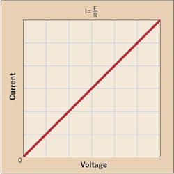
Pure resistance, inductance, and capacitance are all linear. What that means is if we place a sine wave voltage of a certain magnitude across a circuit containing pure resistance, the current in the circuit follows Ohm's Law: I = E ÷ R. So, for a specific value of ohms, the relationship of volts and amperes is a straight line (Fig. 1).
For example, let's say we apply 100V across a 10-ohm resistor. Per Ohm's Law, the current would then be 10A. If we double the voltage to 200V, the resulting current is 20A. For 400V, the current would be 40A, etc.
Inductances
Ohm's Law, as it applies to these types of loads, is expressed as I = E ÷ XL, where XL is the inductive reactance, which is equal to 2πfL, which is equal to ohms. Here, current is directly proportional to the voltage drop and inversely proportional to both the self-inductance and the frequency (f). If the frequency is constant, say 60 Hz, the relationship of voltage and current is a straight line, as we've seen with resistance.
Note that this relationship involves magnitudes only. It does not give the phase relationship between voltage (E) and current (I). Here, voltage leads current by 90°. Also, the ohmic value of XL increases in direct proportion to frequency. So, if frequency is doubled from, say 60 Hz to 120 Hz, XL will also double, etc., thus maintaining a linear relationship.
Capacitances
A similar situation holds for these types of loads. Here, the Ohm's Law equivalent is expressed as I = E ÷ XC, where XC represents capacitive reactance, which is equal to 1 ÷ 2πfC, which is equal to ohms. As with inductance, if the frequency is constant, the voltage and current relationship is a straight line. If, however, the frequency is doubled from 60 Hz to 120 Hz, the XC ohms will be half of what it was at 60 Hz. Nevertheless, the relationship is still a straight line.
Nonlinear loads and current waveforms
Solid-state electronics is based on the use of semiconductors. These materials are totally different in that their response to voltage is not a straight line. In general, the relationship of voltage to current is represented by a curve, as shown in Figure 2. Even this is misleading because each solid-state device will have a unique response curve that is different from that of other types of semiconductor-based devices.
What this means is that with a nonlinear load, you cannot easily predict the relationship between voltage and current — unless you have an exact curve for each device. With equipment containing many solid-state devices, such an approach is impossible.
The only logical way is to use test instruments to plot the individual voltage-current relationships. The test results are often baffling. With an incoming source having a near perfect 60 Hz sine wave, the current will be significantly distorted. However, mathematical (Fourier) analysis of these distorted waves shows that they are made up of the fundamental sine wave — plus one or more harmonic current waves having a frequency that is a whole integer multiple of the fundamental frequency. For example, a 60 Hz fundamental, combined with 180 Hz and 300 Hz waves, will result in a specific type of distorted wave.
Any wave shape can be reproduced exactly by adding together a series of sine waves of particular frequency, amplitude, and timing, although it may require an infinite number of them. Therefore, nonsinusoidal waveforms consist of, and can be broken down into, some finite number of pure sine waves. The chart (click here to see chart) shows how harmonic current waveforms combine with the fundamental to form distorted waveforms.
Voltage waveform distortion
Ohm's Law also helps explain another phenomenon: distorted voltage waveforms caused by distorted current waveforms. Each harmonic current in a facility's electrical distribution system will cause a voltage at the same harmonic to exist when the harmonic current flows into an impedance. This results in voltage harmonics appearing at the load bus. For example, a 5th harmonic current will produce a 5th harmonic voltage, a 7th harmonic current will produce a 7th harmonic voltage, etc.
The equation takes the form of E = (I × Z), where Z is the impedance of an electrical load in the circuit, which in the case of motors, transformers, and similar devices, is mostly inductive. Because a distorted current waveform is made up of the fundamental plus one or more harmonics currents, each of these currents flowing through the impedance will cause a voltage drop across the impedance.
The magnitude of the current and voltage waveform distortion will depend upon the relative size of the nonlinear loads with respect to that system, the type of equipment, and the source impedance. The amount of voltage distortion increases as the percentage of nonlinear loads increases. If you assume the load bus distortion stays within reasonable limits, say less than 5%, the amount of harmonic current generated by the load is generally constant.
Let's talk about system impedance. According to the book, “Electrical Power Systems Quality” (Dugan, McGranaghan, Santoso, and Beaty, ISBN 0-07-138622-X), while the nonlinear load's harmonic currents cause the voltage distortion, the load itself has no control over the amount of distortion. If we put the same load in two different facilities with two different system impedances, we would have two different distortion values.
IEEE 519-1992, “Recommended Practices and Requirements for Harmonic Control in Electrical Power Systems,” recognizes this by basically saying:
-
The control over the amount of harmonic current injected into the system takes place at the end-use application.
-
Assuming the harmonic current injection is within reasonable limits, the control over the voltage distortion is exercised by the entity having control over the system impedance, which is often the electric utility.
While electric utilities everywhere generate very good sine wave voltages, we must remember that the distortion increases closer to the load — and that some loads chop the current into seemingly arbitrary waveforms. When passed through a system impedance, this current can actually cause voltage distortion.
Sidebar: Speak the Same Language
Depending on what industry you're in, the word “harmonics” can mean two different things to two different people. In their book, “Electrical Power Systems Quality,” (ISBN 0-07-138622-X) authors Dugan, McGranaghan, Santoso, and Beaty point out that, by popular convention in the power industry, the majority of times the term “harmonics” is used by itself to refer to the load apparatus; therefore, the speaker is referring to harmonic currents. On the electric utility side, however, many use the term to mean harmonic voltages. So, when talking about “harmonics” with manufacturers, utility people, technicians, etc., make sure everyone is on the same page to avoid any confusion.
Sidebar: All Loads are Not Created Equal
Motors, incandescent lighting, and heating loads are linear in nature. That is, the load impedance is essentially constant regardless of the applied voltage. As seen in Fig. A, the current in AC circuits increases proportionately as the voltage increases and decreases proportionately as the voltage decreases.
The current in these circuits is in phase with the voltage for a resistive circuit, with a power factor (PF) of unity. It lags the voltage by some phase angle for the more typical partially inductive circuit (with a PF commonly between 0.80 and 0.95). And, it leads the voltage by some phase angle in a capacitive circuit.
Nevertheless, this current is always proportional to the voltage. For a sinusoidal voltage, the current is also sinusoidal.
Nonlinear loads, on the other hand, are loads in which the load current is not proportional to the instantaneous voltage. This is because the load current is often not continuous, as shown in Fig. B below. This is the result of the nonlinear load being switched on for only part of the cycle, as in a thyristor-controlled circuit, or pulsed, as in a controlled-rectifier circuit.
Sidebar: Harmonic Current Contributions
Nonlinear loads, such as inverters, solid-state rectifiers used in welders, DC power supplies, variable-frequency drives, and electronic ballasts for lighting are sources of harmonics in the electrical system feeding these loads. There are specific harmonics associated with each item of equipment, and equipment manufacturers can usually provide information on the magnitude and order of harmonics generated by their equipment.
However, depending on the design of the specific item of equipment, the harmonics may vary in frequency and magnitude as load changes occur on the equipment. The Table lists the typical magnitude and order of harmonics for certain loads. The numbers in the harmonic order columns are percentages of the fundamental 60 Hz current.