Explaining Motor Failure
The squirrel cage induction motor's versatility and ruggedness continue to make it the workhorse of the industry, but that doesn't mean it's invincible. Pushing it too hard for too long can cause the stator, rotor, bearings, and shaft to fail. Numerous industry surveys document which parts fail and how, but very little data is available to explain why.
As the industry's approach to maintenance and repair gradually evolves from reactive and preventive to diagnostic and predictive, it's important to pay more attention to root cause failure analysis. Neglecting to do so often will cause your motors to repeatedly fail and cost you valuable resources and time.
Failure surveys. It's common to use the results of failure surveys to diagnose the cause of a specific motor failure, but it can be a costly mistake. Most failure survey data for electric motors is influenced by the particular industry, the geographic location, and the combination of the motors in use. Therefore, specific numbers may not always be relevant.
Not only that, most failure surveys focus on the component that actually failed while neglecting to address the root cause of that failure. For example, such a survey may tell you that a bearing failed, but that isn't the root cause; it's simply the component that failed. The root could be one of several things, but it's not specified.
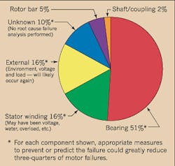
The data provided by the Institute of Electrical and Electronics Engineers (IEEE) study shown in Fig. 1 above is helpful because in addition to identifying failed components, it suggests the most likely causes of failure based on which component failed. However, that's still not enough. It's your responsibility to conduct a thorough analysis to find the definitive root cause of that particular component's failure. These percentages in Fig. 1 may vary based on industry or location.
The real challenge lies in reducing the large category of “unknown” failures. It's these “unknown” failures that make analyzing the entire motor system so critical.
Root cause methodology. Root cause methodology is a step-by-step process for examining a failed motor and its system. It focuses on the stresses that acted upon the failed component. By better understanding these stresses, the service center is more likely to uncover the root cause of the failure.
The five key steps in root cause methodology are:
- Failure mode
The manifestation, form, or arrangement of the failure (e.g., turn-to-turn, phase-to-phase, etc.)
- Failure pattern
How the failure is configured (e.g., symmetrical or asymmetrical).
- Appearance
Examination of the failed part, the entire motor, and the system in which it operates. Care must be taken to inspect all motor parts for damage, contamination, moisture, cracks, or other signs of stress.
- Application
A close examination of the work performed by the motor and the characteristics of those types of loads.
- Maintenance history
A look at the work performed to keep the motor and system in proper operating condition.
In an ideal world, all relevant information pertaining to the application, appearance, and maintenance history would be available prior to the actual inspection of the motor or failed component. In real life, however, the methodology usually consists of inspecting the failed part and the whole motor and then acquiring information about the application, the appearance of the system, and its maintenance history. This sequence is usually driven by the urgency to return the motor to service as well as the availability of application and historical data.
The good news is that the root cause of failure is obvious in some cases. Such examples could be:
-
A balancing weight came loose and struck the winding.
-
The winding is saturated with water.
-
The bearing lubricant is contaminated.
In a case where the root cause isn't as easy to determine, it's imperative that you complete each step of the methodology.
Summary of motor stresses. Most motor failures are caused by a combination of various stresses that act upon the bearings, stator, rotor, and shaft. If these stresses are kept within the design capabilities of the system, premature failure shouldn't occur. However, if any combination of the stresses exceeds the design capacity, the life of the system may be drastically reduced and catastrophic failure could occur.
These stresses are classified as follows:
- Bearing stresses
Thermal, dynamic and static loading, vibration and shock, environmental, mechanical, electrical
- Stator stresses
Thermal, electrical, mechanical, and environmental
- Rotor stresses
Thermal, dynamic, mechanical, environmental, magnetic, residual, and miscellaneous
- Shaft stresses
Dynamic, mechanical, environmental, thermal, residual, and electromagnetic
For a more detailed summary of these stresses, see Table 2.
Analysis of the motor and system. Surrounding the motor is a system that consists of the power supply, mounting, coupling, and driven equipment. The environment, including the ambient temperature, acts as an umbrella that covers all of the system's elements. Even the end product or process can be considered part of this system. (See Fig. 2).
Many factors that affect the system will also affect the motor and may contribute to the motor failure and vice-versa. Failure to consider each of these elements of the motor system could lead to an incorrect diagnosis of the root cause of failure. Conducting a failure mode effect analysis (FMEA) of the complete system is an effective approach. The idea is to determine what the possible failure modes are for a component and then determine how that failure can affect the system where the component resides. This will offer at least some of the possible scenarios that can lead to a motor failure.
It's important to note that a number of failure mechanisms can cause the same part to fail with a common mode and pattern of failure. As examples, improper voltage, too much load, blocked ventilation, excessive cycling, and excessive heat can all produce the same type of winding failure. It's not always possible to correctly identify the problem without considering the entire system.
In many cases, arriving at the correct conclusion requires a process of elimination driven by the collection of accurate data and facts associated with the system. Failure to eliminate the root cause will usually ensure expensive downtime and repeated motor failures. A classic example is the repeated replacement of failed bearings without ever trying to assess the root cause of failure.
Arriving at the correct conclusion. When analyzing a motor failure, it's important to not make assumptions. The service center rarely knows much about the motor application, much less the power supply and/or maintenance history. The individual dealing with the service center may not be the person who removed the motor from service or the operator who is familiar with the motor or its application, meaning that it's imperative those individuals compile all of the facts before concluding anything.
Incorrect, incomplete, or even misleading information is the norm. But it doesn't have to be that way. Never assume a piece of evidence exists just to force the conclusion to fit the facts. When a conclusion is built around erroneous information mingled with facts, the root cause of failure is seldom correct. The result will be additional failures or the assignment of blame to the wrong parties.
Bonnett is an education and technology consultant, and Yung is a technical support specialist, both for EASA in St. Louis.