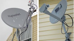
If you're looking for new revenue streams or a way to expand your business reach, adding satellite work to your repertoire isn't a bad idea. Electricians are well positioned to pick up these jobs because they already have most of the tools and expertise to do satellite dish work. In fact, troubleshooting techniques are similar to solving housewiring problems — if you understand the behavior of higher frequencies involved. But before spinning off into the world of dishes, you should start by understanding the basic technology behind these types of systems.
Today's satellite infrastructure, for our purpose as electrical designers and installers, provides TV and Internet access to homes and businesses throughout the world. Although satellite is perceived by many to be in competition with cable, they are actually two sides of the same coin in that a cable head typically picks up its signal from a dish array. Even at a one-family satellite dish-equipped dwelling, the signal is brought to the receiver by cable. On a large-scale, big hotels and office buildings — beyond the range of conventional cable — require complex and sophisticated dish distribution systems to become fully connected.
How dish systems work. We all know that the parabola is one of Euclid's conic sections, the curve corresponding to that cross-section of a cone, which has the characteristic of reflecting incoming parallel rays to a single focal point. The satellite dish is the reverse of a parabolic floodlight in which the reflector picks up light from a single source and reflects out parallel light rays. Depending on the size of the dish, there is a significant amount of passive amplification that takes place at this stage. But the signal could never make it to the building via cable. It would disappear within 2 to 3 feet due to capacitive and radiation losses characteristic of these incredibly high microwave frequencies.
After it arrives at the dish, the signal transmitted by a satellite transponder is reflected and propagated by a circular or rectangular tube, which is part of the feedhorn. This tube, known as a waveguide, has dimensions based on the wavelength of the signal. Its purpose is to confine and funnel the signal, which zigzags or bounces wall to wall along its path. Thus, the feedhorn is a channel that brings the signal to a pickup probe attached to the low noise block (LNB). This LNB provides further amplification and, by combining it with an appropriate frequency generated by a local oscillator, reduces the carrier to a lower frequency so it can travel by coaxial cable to the receiver inside the building.
Also located inside the feedhorn is a polarizer. Satellite operators found that they could double the number of available channels by sending two separate signals on each frequency. Vertically and horizontally polarized signals can occupy the same frequency, but the desired signal has to be separated out within the feedhorn. Early models of satellite dishes required a servo motor to rotate a polarizer as the user selected different channels, but today the same thing is accomplished via electronics.
Since the feedhorn contains active components, power supply voltages are required at the dish. As is the case in a lot of low-voltage equipment (e.g., centrally supervised fire alarm, telephone, or cable TV), a power supply voltage has to be sent out to the dish, coexisting with the signal but traveling in the opposite direction. Considering the fact that the feedhorn has no power supply of its own, this voltage is DC. In one system, two different voltage levels (13V and 17V) inform the polarizer inside the feedhorn of the desired version (horizontal or vertical) — or in the case of circular polarization, clockwise or counterclockwise — thereby doubling the number of channels available.
The signal, reduced to a workable frequency and correctly polarized, travels into the building where it enters the receiver. The receiver perform four major operations:
-
The desired channel is selected.
-
If the signal is encoded so that only paying customers have access, it is decoded by means of interaction between an accompanying data stream and the “smart card” inserted in the receiver's access slot.
-
Menu interactivity and graphics become available by means of one or more microchips.
-
The signal frequency is further reduced to a level that can be processed into usable audio and video by the TV.
From the receiver, the signal has to be brought to the TV by means of a short length of coaxial cable or color-coded RCA jacks, which can provide stereo signals.
Installation basics. To install a satellite dish system, you must first perform a site survey. The microwave carrier from the satellite cannot pass through hills, buildings, trees, or other solid objects. Therefore, the dish has to be mounted high enough to access the signal. You can usually obtain excellent reception by a simple wall or roof mount.
Typically, the customer signs up for TV or Internet satellite dish service either online or at a retail store. The primary vendor turns the installation over to a local technician who makes an appointment with the customer. Alternately, the customer performs the installation or hires a trusted electrician, often in the course of new building. The installation usually takes about half a day — or less if the technician has a helper.
The most challenging part of the job is mounting and aiming the dish. If the dish isn't solidly mounted — or if the aiming is even a little off — a good picture may be acquired initially, but any rain or snow will degrade future performance. Microwave propagation is severely compromised by atmospheric moisture. Ice buildup on the dish distorts the shape of the reflector.
The dish can be aimed and tweaked using an on-screen signal strength meter, which usually entails having a helper inside the building yelling out to another worker on a ladder or on the roof. Alternately, various instruments can be hooked directly to the dish. These range from an inexpensive satellite finder to a spectrum analyzer for the more advanced technician.
The best installation can be severely compromised by flawed cabling. Remember that electrical signal transmission acts in different ways, depending on the frequency. The highest frequencies (in the 11-GHz range) are taken care of in the feedhorn/LNB region of the dish assembly. A head that doesn't seem to produce an output, assuming it is correctly aligned and is receiving the correct supply voltage(s), may have fallen victim to water infiltration.
Coaxial cable usually comes in 1,000-foot reels. The terminations are crimped on using a simple hand tool. When connecting to the receiver or TV set, snug these connectors hand tight to avoid damage. A full line of wall box faceplates, couplings, and splitters is readily available.
For other technical details, refer to the owner's manual. The major providers of satellite services, such as Dishnet and DirecTv, provide excellent installation materials with complete aiming and cabling instructions.
Applicable NEC rules and guidelines. It's plain to see that many satellite installations are not grounded correctly, if at all, including those performed by professional installers. Of those that are, a large number have had an isolated (floating) ground rod installed with no thought of bonding back to the power system neutral as required by the National Electric Code (NEC). Most working electricians and designers understand that all grounds in a single building (including outbuildings supplied by the same service) have to be bonded to prevent flashover (fire hazard) and voltage difference (shock hazard).
A major source of electric shock is when low-voltage wiring, including satellite coaxial lead in, comes in contact with 120V or 240V wiring and becomes energized. Therefore, NEC mandates certain separations and clearances that are contained in 810.18.
810.20 covers the Antenna Discharge Unit. Each lead-in conductor from any outdoor antenna, including a satellite dish, must have one of these units, which have coaxial connectors for input and output and a grounding conductor lug. The antenna discharge unit must be located inside or outside the building, nearest the point of entrance and not near combustible material.
The dish must be grounded. Where it swivels or turns for aiming, all articulating parts should be separately bonded and connected to a bare or insulated, solid or stranded 10 AWG copper grounding/bonding conductor, which goes to one of the Code-sanctioned grounding means, such as a water pipe within 5 feet of entry to the building. Verify that the electrical service was bonded to this piping.
This grounding/bonding conductor, for one- and two-family dwellings, cannot be longer than 20 feet, and should be as short as possible. Any bends should be gradual and kept to a minimum. If the distance is greater than 20 feet, drive a ground rod in close proximity. Attach the conductor to the ground rod with a ground rod clamp listed for direct burial, and drive the ground rod below grade. Using a second ground rod clamp, attach another conductor — this time 6 AWG bare or insulated, solid, or stranded copper — and tie into the building's ground electrode system.
As you can see, dish installation requires specialized knowledge, including compliance with NEC grounding and cabling requirements. Armed with the right knowledge and tools, electricians can pick up this work in the course of new construction or remodeling, increasing the size of their contract without too much effort.
Herres is a licensed master electrician in Stewartstown, N.H.


