Diagnosing Power Problems at the Receptacle
When clients call you because operating problems on pieces of their 120V equipment cause them to suspect their facility's power supply, you have to decide where to start your investigation. Don't proceed directly to the distribution panelboard that feeds the circuit first. Instead, first look at the outlet nearest the problem equipment.
The next step is deciding what measurement to make, but you only have three options to choose from: phase-to-neutral voltage, neutral-to-ground voltage, and phase-to-ground voltage. With these measurements, you're well on your way to answering the following questions:
- Is the outlet wired wrong?
- Is the branch circuit too heavily loaded?
- Do sensitive electronic loads have the voltage they need?
Believe it or not, you can get that much information from such fundamental yet simple measurements. The three measurements, all taken at one outlet, can provide you with a solid understanding of the facility's electrical supply and help you identify miswired receptacles.
| See Also: EC&M eBook: A Lethal Combination Get these Real-world examples of why electricity and water don't mix. Download now. |
Miswired Receptacles
You might think the vast majority of 120V receptacles are wired correctly, but that isn't the case. In fact, it's not uncommon to find the hot and neutral wires or the neutral and ground wires reversed or shorted.
These conditions can often go undetected for a long time. Because many loads aren't sensitive to polarity, they operate quite well with the neutral and hot reversed. Electronic loads, for example, are generally indifferent to AC polarity because their internal power supplies are simply converting AC to DC.
On the other hand, the operation of sensitive electronic loads, such as computer equipment and instrumentation, is dependent upon a clean ground — one with no load current and no voltage on it. A single reversal of a neutral and ground can compromise the entire ground system.
Office Troubleshooting Scenario
You could make a visual inspection of each receptacle for correct wiring, but that would be time intensive. It's much easier to make measurements with a digital multimeter (DMM) or clamp-on meter with voltage measurement capability.
Let's take a look at a troubleshooting scenario at an office. Suppose you made the following voltage measurements during working hours and under normal load conditions:
Phase (hot)-to-neutral voltage. This measurement is the voltage the load will see. Typically on a 120V circuit, you should get a reading of between 115V and 125V. Let's suppose you measure 118.5V.
Neutral-to-ground voltage. This is a measurement of voltage drop (also called IR drop). It's caused by load current that flows through the impedance of the neutral wire. Let's suppose you measure 1.5V.
Phase (hot)-to-ground voltage. You can think of this as the source voltage available at the receptacle. Let's suppose you measure 120V here.
Now the analysis begins.
Analyzing the Measurements and Spotting Miswiring
Your first conclusion is that the hot-to-neutral voltage (118.5V) is higher than the neutral-to-ground voltage (1.5V), as you would expect. But upon further analysis, you see the hot-to-ground voltage (120.0V) is equal to the sum of the hot-to-neutral voltage (118.5V) and the neutral-to-ground voltage (1.5V). This raises the questions, Are these readings normal? and, Is the outlet wired correctly?
As stated earlier, the most common miswiring conditions are reversed hot and neutral wires and reversed or shorted neutral and ground wires. So how do you spot these conditions?
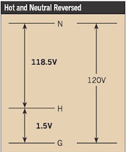
Reversed hot and neutral wires. Measuring hot-to-neutral voltage by itself doesn't tell you if those wires are reversed. You must measure neutral-to-ground or hot-to-ground voltage. If the neutral-to-ground is 120V and the hot-to-ground is a few volts or less, then the hot and neutral wires are reversed (Fig. 1).
Neutral-to-ground connection. Some neutral-to-ground voltage should be present under load conditions, typically 2V or less. If the voltage is zero with a load on the circuit, then check for a neutral-to-ground connection in the receptacle, whether accidental or intentional.
Reversed neutral and ground wires. To check for reversed neutral and ground wires, measure the hot-to-neutral and hot-to-ground voltages under load. The hot-to-ground reading should be higher than the hot-to-neutral reading. The greater the load, the more difference you'll see.
If the hot-to-neutral voltage measured under load is greater than the hot-to-ground voltage, the neutral and ground are reversed. This should be corrected immediately.
Hot-to-ground voltage. This reading should be the highest of the three readings. The ground circuit, under normal, non-fault conditions, should have no current and, therefore, no IR drop on it.
Think of the ground connection as a wire that runs back to the source (main panel or transformer), where it's connected to the neutral. On the receptacle end of the ground path, which is where you're making your measurements, the ground isn't connected to any voltage source. So the ground wire is like a long test lead back to the source voltage.
When you connect the load at the receptacle, the hot-to-ground receptacle source voltage should be the sum of the hot-to-neutral voltage (the voltage across the load) and the neutral-to-ground voltage (the voltage drop on the neutral wire all the way back to its connection to the ground circuit) (Fig. 2 on page 34).
Testing for Voltage Drop
On an ideal circuit, there should be no voltage drop. The less the voltage drop, the more “stiff,” or reliable, the source. In reality, however, there is always some voltage drop through the wiring system that can be brought on by one of the following:
- Wire gauge will affect voltage drop. The smaller the wire gauge, the higher its impedance.
- The length of the run is also a determinant. The longer the wire run on the branch circuit, the greater the impedance and the greater the IR drop.
- The amount of load also affects voltage drop. The more heavily loaded the circuit, the greater the voltage drop. (V= I×R, so the more current, the greater the voltage drop.)
Since the first two factors are normally “fixed” in an existing circuit, it's the last factor you can readily address. Basically, you're asking if the circuit is overloaded.
To measure voltage drop, you need to use the neutral-to-ground voltage measurement. To explain this voltage, let's run an “experiment.”
Suppose you plug a 1,500W hairdryer into a receptacle on a lighted loaded circuit. It should draw about 12A, enough to create a noticeable voltage drop. You make hot-to-neutral, neutral-to-ground, and hot-to-ground measurements (Table above). By analyzing these readings, you can see that the neutral-to-ground voltage increases with loading, just like voltage drop (the third factor noted above).
Also, notice how the hot-to-neutral voltage drop (5.2V) almost equals the sum of the neutral-to-ground and hot-to-ground voltage changes (2.4V+2.7V= 5.1V). The combined black and white wire IR drops subtract from the voltage available to the load (the hot-to-neutral voltage). The white wire IR drop is as easy to measure as neutral-to-ground voltage, but the increased current causes an IR drop on the black wire as well as the white wire. This black wire IR drop (2.4V) is measurable by taking the difference between the no-load hot-to-ground voltage (121.6V) and the load hot-to-ground voltage (119.2V).
In reality, it's not that easy to switch all the loads on and off to make this measurement, which is why the neutral-to-ground voltage measurement is so useful.
In most office environments, a typical reading of neutral-to-ground voltage is about 1.5V. If the reading is high (above 2V to 3V), then the branch circuit might be overloaded. Another possibility is that the neutral in the panel is overloaded. To accommodate PCs and other electronic loads with switch mode power supplies, the neutral feeder should be at least as large as the phase conductors and preferably twice as large.
Measuring Peak Voltage
The receptacle outlet is the point in the wiring system farthest from the source. That means it's the most vulnerable to voltage supply problems. To the single-phase load that's plugged into it, it's the only point in the system, reliable or not, that matters.
All of the previous measurements were in rms values. However, you need to measure the peak value as well because electronic loads care about the peak value, since that's what they use to power their AC-to-DC conversion circuits. When almost all of the loads on a circuit are electronic, they're all drawing power at the same time from the peak of the wave. As a result, the sine wave tends to become “flat-topped.” This makes it harder for electronic power supplies to charge. An rms reading alone won't spot this problem.
The normal peak, assuming that the AC voltage is more or less a perfect sine wave, is 1.4 times the rms voltage. So for a 120V circuit, that equals about 168V.
Many meters will specify a 1-ms rms peak or peak hold option. Since a half cycle of 60 Hz is about 8.3 ms, the 1-ms rms peak function should capture the half-cycle peak.
If everything tests okay at the receptacle, you can safely conclude that something other than incorrect receptacle wiring caused the equipment problems. The problem might be voltage fluctuations or transients caused by other issues in the facility or on the electric utility supply system. Of course, it could be the load itself that's acting up.
A next step would be to connect a voltage-recording device to the receptacle and check the voltage over time.
Smith is a product specialist with Fluke Corp., Everett, Wash.
Sidebar: Working Safely
The voltage and current present in electrical power systems can cause serious injury or even death. At the very least, follow these guidelines when taking measurements:
-
Use safety equipment like safety glasses, insulated gloves, and insulating mats.
-
Be sure that all power has been turned off, locked out, and tagged in any situation where you will be in direct contact with circuit components. Also make sure that the power can't be turned on by anyone but you.
-
Read and understand all of the applicable manuals before applying the information noted in this article. Take special note of all safety precautions and warnings in the instruction manuals.
-
Don't use instruments on applications for which they aren't intended. Also, always be aware that if you don't use the equipment in a manner specified by the manufacturer, the protection provided by the equipment may be impaired.