Correctly installing capacitors at the terminals of your motors can lower reactive power requirements and increase system power factor.
Induction motors are the primary source of rotary power in the United States, and they require reactive and real power to operate. The reactive power, which is measured in volt-amperes reactive (VARs), sets up the magnetic fields within the motor, while the in-phase power, which is measured in watts (W), does the work of rotating the shaft. As such, both VARs and watts flow through the motor supply conductors. The VARs don't consume energy. Instead, they build up energy from the generator and momentarily store it within the motor's magnetic fields. These fields collapse during the next half cycle and return the magnetic energy to the electric power system.
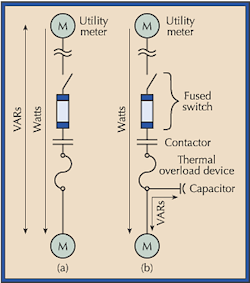
The power flow to the motor is the vector sum of the real power and the reactive power (VARs). The VARs increase the kilovolt-ampere (kVA) demand required from the motor, which is measured at the electric utility meter (Fig. 1a, right). However, this doesn't increase the wattage load. The W/VARs ratio is known as the power factor (PF). Utilities have long charged customers for the increased kVA demand, arguing they must have generators, transformers, and lines large enough to carry both the in-phase current and lagging current, even though the VAR energy is returned to the electric power system every half cycle.
You can reduce the kVA demand by installing PF correction capacitors on the load side of the utility meter (Fig. 1b above). Capacitor current leads rather than lags the voltage (in electric degrees). Thus, capacitors are effectively a source of leading reactive power, measured in VARs-leading, or volt-amperes capacitive (VACs). Capacitors connected to the electric power system on the load side of the utility meter merely trade reactive energy back and forth with the magnetic fields, such as motor fields, within the electric power system. The connection produces a net effect of reduced kVA demand measured by the utility meter.
As capacitors are connected closer and closer to the motor's magnetic field, the amount of I2R heat lost in the wires between the motor and the capacitor is reduced. Connecting the capacitor to the terminals of the motor at the motor junction box minimizes the conductor heat loss as much as possible.
Sec. 460.8(C) of the NEC requires you to provide capacitors with disconnecting means, but it makes an exception for capacitors connected on the load side of the motor controller (Fig. 1b on page 12). Because a motor capacitor disconnect switch is unnecessary, the motor capacitor installation is much less expensive. Cutting expense is important when you consider the cost (in $/kVAC) of installing larger capacitor banks that provide VAC for groups of inductive loads. This is true because the $/kVAC of small capacitors is relatively high when compared to the $/kVAC of larger capacitors, and even more-so when compared to the low $/kVAC cost of higher voltage capacitors. But connecting the capacitor at the motor or at the load side of the motor starter provides a built-in capacitor controller that de-energizes the capacitor when not in use.
There are, however, limitations on capacitor size when connecting capacitors this close to the motor terminals. These limitations are products of self-excited motor overvoltage (of as high as two times source voltage) and excessive inrush current (of as much as 20 times normal full-load current). Subsequent transient torque caused by out-of-phase reclosing before the capacitor can discharge can also play a part in limiting capacitor size.
When it comes to capacitors, how large is too large? If the maximum size capacitor is not printed on the motor nameplate or in the manufacturer's motor data, then it's a good idea to keep the capacitor small enough that the capacitor current doesn't exceed the motor no-load current. Test the current with a clamp-on ammeter. The resulting maximum capacitor size will normally be approximately 15% of the kVA rating of the motor, but this capacitor will not improve the motor PF to greater than about 95%.
Connection of the capacitor on the motor side of the thermal overload reduces current through the overload because the reactive current flows only between the motor and the capacitor, and no longer flows through the overload. NEC 460.9 and valid engineering require that the overload rating be reduced in ampere trip rating so that it can still effectively protect the motor from overload current. The reduction in overload size will vary from 10% to 35%, depending upon the motor speed and horespower.
To know for sure the correct new overload rating for each motor, rather than becoming baffled by numerous tables and formulas that attempt to predict the best percent reduction in overload requirement, the most accurate method for determining the reduction for each specific motor involves using one of the fine small power analyzer meters available today. Simply measure the real and reactive fully loaded motor current drawn through the protective overload device before and after capacitor installation, and reduce the overload ampere rating by the amount of overload current reduction caused by the capacitor installation. The meter readings will show that reactive current sums vectorially as an out-of-phase current from motor real load current. As a check, the final ampere value of the overload selected should not exceed the fully loaded motor current measured through the overload multiplied by the appropriate percentage from 430.32.
