Common Misunderstandings in Overcurrent Protection
Do you know the facts about circuit protection, or have you just been relying on what you hear around the shop?
As an electrical contractor, system designer, plant electrician, or electrical inspector, you're responsible for providing safe and Code compliant installations. This mindset is probably best stated in the IEEE Buff Book: “The objectives of electrical system design and coordination are to prevent injury to personnel, to minimize damage to the system components, and to limit the extent and duration of service interruption whenever equipment failure, human error, or adverse natural events occur on any portion of the system.” However, these stated goals are often impeded by misunderstandings of equipment performance and/or applications.
Misunderstanding No. 1: It's OK to apply 100% rated molded case circuit breakers (MCCBs) and standard (non-100%) rated MCCBs in the same way.
A requirement in 210.20(A) of the 2002 NEC states “the rating of the overcurrent device shall not be less than the noncontinuous load plus 125% of the continuous load.” In other words, you shouldn't load the overcurrent device at more than 80% of the continuous load. An exception permits you to rate the overcurrent device for 100% of the noncontinuous and continuous load “where the assembly, including the overcurrent devices protecting the branch circuit(s), is listed for operation at 100% of its rating.” A similar requirement appears in 215.3 for feeders. Consider the following differences between standard devices and those rated for 100%, and their application in equipment.
A 100% rated MCCB is intended for continuous operation at 100% of its marked rating in an enclosure. That means it will carry 100% of rated current without overheating or tripping when enclosed. UL-Listed, 100% rated MCCBs are marked “Suitable for continuous operation at 100% of rating only if used in _____.” The blank identifies the enclosure or equipment in which they may be used.
Standard MCCBs are neither rated 100% nor marked as indicated above. All MCCBs are tested to carry 100% of rated current continuously without overheating or tripping when connected with conductors sized for their current rating. However, that test is done in open air without an enclosure. When standard MCCBs are enclosed — and especially when they're group-mounted, as in a panelboard — they're applied at 80% of their rating. In temperature tests within panelboards, switchboards, circuit breaker enclosures, and similar equipment, MCCBs are loaded to 80% of their rating unless they're 100% rated.
Given this information about ratings, you might wonder if 100% rated and standard MCCBs trip with the same overcurrent conditions. To answer this question, you must be aware of the following three MCCB considerations:
- Rating
Imagine a 400A MCCB connected with two 3/0 AWG copper wires as permitted by the NEC. Whether 100% rated or standard, the circuit breaker must carry 400A in an open-air test without tripping or overheating. Both types must trip within 2 hr when carrying 135% of rated current, which is 540A. And both are safe and permitted under the NEC when applied within their ratings and markings because the load is known and conductors are sized to carry current within the characteristics of the MCCB.
- Characteristic curve.
Both breakers are rated 400A and have identical tripping characteristics under open-air testing. But the time-current characteristics for the 100% rated MCCB may be slightly different to allow for higher temperatures because it can carry a higher current when mounted in an enclosure.
- Temperature
What differentiates the two types of breakers is the fact that the 100% rated MCCB must also be tested in an enclosure, again with two 3/0 AWG conductors and carrying 400A. If temperature rises are above those permitted for the standard MCCB but within acceptable limits for the 100% rated unit, you may have to use conductors with insulation rated at 90°C. When the standard MCCB is tested in an enclosure, it will be connected with two 3/0 AWG conductors and will carry 320A, or 80% of rated 400A.
Based on these differences, you need to take several things into account for the various possible applications. For a branch circuit, you would determine the load and size the circuit as indicated in Art. 210. Then you would select the conductor size as indicated in 210.19. Finally, you would determine the overcurrent protection in accordance with 210.20.
Now, imagine a circuit with a 300A noncontinuous load plus a 50A continuous load. According to 210.19(A), you must size the conductors for 363A if you're going to use a standard overcurrent protective device. You would also select two 3/0 AWG copper conductors. Per 210.20, you would select a 400A MCCB.
If you intend to use a 100% rated MCCB, you would size the conductors for 350A and use two 2/0 AWG copper conductors. The 100% MCCB may be marked to require 2/0 AWG conductors with insulation rated 90°C. Then, per 210.20, you would select a 350A, 100% rated MCCB. For a feeder, the requirements of 215.2 and 215.3 apply. For service-entrance conductors, 230.42 applies.
Note that the 100% rating doesn't apply when you use a MCCB for motor circuit protection under Art. 430.
Misunderstanding No. 2: It's possible to determine series ratings through a set of calculations.
Questions about whether you can determine series ratings by calculation rather than the extensive test program used through industry standards are common. Beside the fact that any such calculations would bypass industry standards and not comply with NEC requirements, there are definite technical reasons why calculations aren't adequate (Sidebar below).
The standardized test program for series ratings first appeared in 1970 in UL 489 Standard for Molded-Case Circuit Breakers, followed by a companion test program in UL 67 Standard for Panelboards. This test program allows the application of an MCCB where the available fault current is greater than the MCCB's interrupting rating, but only if the MCCB is protected by a circuit breaker or fuse upstream on its supply side.
This mandatory test program calls for the completion of the following test steps before the “series rating” may be applied under 240.86:
-
The downstream MCCB must be listed.
-
The upstream circuit breaker or fuse must be listed and have an interrupting rating at least equal to the series rating.
-
The series combination is short-circuit tested at the series rating.
-
The series combination is short-circuit tested at a lower short circuit value at which the upstream device may not provide the needed protection, or where the upstream circuit breaker may not operate in time to protect the downstream MCCB. Alternatively it would be the value at which the upstream fuse would just reach its threshold of current limitation.
-
The series combination is short-circuit tested in the equipment in which it will be applied. The tested rating is then marked on that equipment.
In the above context, the term “series combination” applies to the two devices — upstream circuit breaker or fuse and downstream MCCB — connected together and considered as a unit.
Misunderstanding No. 3: No extra precautions are necessary when installing equipment in corrosive environments.
Electric equipment installed in environments that contain corrosive gases or liquids are subject to severe deterioration, which can lead to unexpected shutdown. Deterioration can also compromise protection levels and lead to fire. Properly enclosed and housed equipment will prevent these unwanted occurrences.
Facilities that contain corrosive atmospheres include animal confinement areas, meatpacking plants, rendering plants for animal products, and sewage treatment plants. The corrosive substances found in the atmospheres in these facilities include ammonia, sulfides like hydrogen sulfide, sulfur dioxide, sulfates, chlorides, chlorates, methane, and uric acid. These substances most frequently exist in a gaseous state. However, hosing down areas during cleaning will spread some liquids and bring them into contact with electrical equipment.
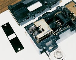
Electric parts most affected are those fabricated of bare copper, aluminum, and silver compounds (Photo 1). Many current-carrying parts are fabricated of copper or aluminum compounds. Silver is commonly used in electrical contacts found in circuit breakers and in plating of bus bars to provide good electric contact. Electronic components are especially susceptible to damage by corrosive atmospheres because they're small. Conformal coating generally used to protect printed circuit boards from dust doesn't protect against corrosive gases.
Photo 2 illustrates flaking of silver plating on bus bars. The areas in which flaking has occurred are no longer protected, which leads to further corrosion and poor connections. Such flakes can also fall from the bus bar and cause a short circuit or arc flash condition. In this case, the flaking was discovered after the electronic trip unit of a main circuit breaker was damaged by corrosion and tripped, causing an unexpected facility shutdown.
In 547.5(C), the NEC addresses the issue of corrosion for agricultural buildings. These buildings are sometimes installed in locations and under conditions in which inspection isn't available and there is little understanding of the hazards involved. The NEC doesn't address packing and rendering plants, except with a general statement in 110.11. There are generally no live animals in these plants, but the animal products that generate corrosive atmospheres are present. No special coverage appears in the NEC for sewage treatment plants either, despite the fact that the problems related to corrosion in these environments repeatedly occur. Several options exist for protecting equipment from corrosive environments, including the following:
-
Install it in locations away from the corrosive environment.
-
Locate equipment inside enclosures intended for the environment, such as sealed-4X enclosures suitable for the gases in the environment.
-
Install it inside separate electrical equipment rooms that are sealed and maintained with a positive pressure and where the air supply is uncontaminated.
Proper installation and housing for electrical equipment will avoid unexpected shutdown and expensive replacement or repairs that can result from corrosion during the time the facility is in operation.
Misunderstanding No. 4: Handle ties provide the same operation as internal common trip.
Handle ties provide an acceptable method of linking operating handles of several single-pole circuit breakers together so they'll switch the tied circuit breakers together. Although good reasons exist for using handle ties, such as in multiwire branch circuits, the method in which a handle tie functions is often not well understood. And in some cases, application of handle ties may lead to unnecessary hazards.
It's important to understand the difference between the handle tie feature and the common trip feature. Handle ties fasten the handles of two or more single-pole circuit breakers together. With handle ties installed, all of the poles are switched on and off together. However, if one pole trips because of an overload or short circuit, the handle tie doesn't cause the connected poles to trip. The condition can leave one pole tripped and the other tied poles energized.
Multipole circuit breakers with common trip will switch all poles on and off together. They'll also trip all poles simultaneously when an overload or short circuit occurs on any of the poles. In this case, all poles operate together regardless of whether the circuit breaker is switched manually or opens automatically because of overcurrent.
It's often impossible to determine the difference between the common trip 2-pole circuit breaker and two single-pole circuit breakers with handle ties unless you're familiar with the product design. The potential hazard arises when one pole trips and another pole remains energized. It's especially hazardous if someone assumes that all poles are tripped and open when only one pole is open.
Consider a multiwire branch circuit as described in 210.4. Handle ties are frequently used in multiwire circuits. These circuits supply only line-to-neutral loads unless they supply only one piece of equipment or unless the overcurrent device opens all conductors simultaneously (common trip). By the definition in Art. 100, multiwire branch circuits have a grounded conductor with equal voltage between it and each ungrounded conductor. When one pole trips due to overcurrent, the remaining pole(s) is connected in a closed circuit with the grounded circuit conductor.
Alternatively, consider a straight 240V circuit with no grounded circuit conductor. When one pole trips, the remaining pole(s) is energized with no return path through a circuit conductor. The pole will continue to serve the fault unless tripped or opened manually.
The fundamental requirement of 240.20(B) is that the circuit breaker shall open all ungrounded conductors of the circuit. In other words, it calls for common trip. The section provides the following exceptions to allow the use of single-pole circuit breakers with handle ties:
-
In multiwire branch circuits
-
On circuits with line-to-line connected loads of grounded single-phase systems and on 3-wire DC circuits
-
With line-to-line loads in 3-phase, 4-wire systems and 2-phase, 5-wire systems
In light of the fact that handle ties don't provide for common trip and the fact that the fundamental requirement is for common trip, it seems most reasonable to apply only circuit breakers with common trip in the second and third items above, where line-to-line loads are served. That means eliminating those two items as exceptions.
The National Electrical Manufacturers Association (NEMA) has proposed eliminating these two items from the NEC, and the Code Making Panel is considering it. Acceptance of that proposal will require the installation of common trip circuit breakers in circuits serving line-to-line loads and require that all poles clear the circuit simultaneously.
The requirements of 240.20(B) relate only to circuit breakers. They don't affect fuse applications. The separate disconnect for fuses is quite different from the integrated functions of a circuit breaker. Many users believe all poles of a circuit breaker open when one pole opens, without fully understanding the function of handle ties. Common-trip circuit breakers are readily available and are the standard for 2- and 3-pole circuit breakers.
Handle ties have an appropriate place in providing a means for protecting multiwire branch circuits. However, they aren't a replacement for common trip and shouldn't be perceived that way.
Specifying a safe design isn't easy when you're confronted by several of the misconceptions that serve to further muddle the situation. However, taking the time to separate the truth from the myth will help you provide an environment that's not only safe for workers but reliable and low-maintenance.
Gregory is manager, industry standards, overcurrent protection for Schneider Electric/Square D, Cedar Rapids, Iowa.
Sidebar: Past Series Rating Methods
Prior to 1970, series ratings had been applied by means of calculations in what were termed “cascade ratings.” No formal method had been specified for these cascade ratings, and they were unreliable. The formal test program replaced these informal ratings in order to avoid unreliable installations. The requirement for marking of tested series ratings on end-use equipment first appeared in the 1990 NEC.
The “up-over-down method” was promoted by some fuse manufacturers and applied as an alternative to testing until about 1993 when a paper titled “Interplay of Energies in Circuit Breaker and Fuse Combinations” appeared in the May/June 1993 issue of IEEE Transactions on Industry Applications and cast doubt on the viability of the method.
This paper, authored by engineers Bernie DiMarco and Steve Hansen, clarified that the up-over-down method didn't accurately determine protection for the downstream MCCB, especially for faster operating MCCBs. One reason cited was that the method couldn't predict performance if the downstream MCCB contacts separated prior to the time the fuse cleared. Information isn't available to predict when MCCB contacts will separate, even though time-current curves show the longest time that the MCCB will take to clear the circuit by itself. With contacts beginning to open, the MCCB is, in fact, absorbing a portion of the energy of the short circuit that the upstream fuse won't see. Without the full energy, the fuse will operate slower than anticipated by the method. So the degree of protection is indeterminate.