Calculating Arc Flash Energy Levels

While not a major topic of consideration when designing and maintaining facilities in past years, code-enforcement bodies have become increasingly aware of the danger of arc flash incidents associated with working on live electrical gear. As a result, facility managers and their consulting engineers are paying more attention to arc flash analysis.
While the National Electrical Code (NEC) requires only a generic label to warn of the possibility of arc flash danger on all equipment that is subject to arc flash hazards, NFPA's “Standard for Electrical Safety in the Workplace” (NFPA 70E-2004) goes a step further, requiring that, “A flash hazard analysis be done in order to protect personnel from the possibility of being injured by an arc flash.” This standard also requires that the analysis include a calculation of the flash protection boundary of each piece of equipment and determination of the required personal protective equipment (PPE) at the appropriate working distance for each piece of equipment.
Both NFPA 70E and IEEE 1584, “Guide for Performing Arc-Flash Hazard Calculations,” prescribe their own methods of calculation for determining the available arc flash energy at a particular piece of equipment. However, for both methods, typical working distances are given in Table 3 of IEEE 1584-2002.
Calculating arc flash energy
There are two distinct mathematical methods of calculating the available arc flash energy present at a specific piece of equipment — both of which are detailed in Annex D of NFPA 70E.
The first method, commonly referred to as the NFPA 70E equation for an arc flash in a cubic box, is:
EMB = 1038.7 DB-1.4738 × tA [0.0093 F2 0.3453 F + 5.9673]
Where EMB is the arc flash energy, DB is the working distance (from Table 3 of IEEE 1584), tA is the duration of the arc, and F is the short-circuit (or fault) current. This equation uses inches for distance measurements, and gives results directly in calories per centimeter squared (cal/cm2).
The cubic box is the commonly used equation (as opposed to the open air equation) because this equation most accurately approximates the behavior of an arc flash event within a standard piece of electrical equipment (switchgear, fused switch, etc.). However, this equation is only valid over the limited range of conditions where the short-circuit current (F) is between 16kA and 50kA.
A broader range of short-circuit values is effectively modeled by using the IEEE 1584 set of equations:
log [En] = k1 + k2 + 1.081 log [Ia] + 0.0011 G and E = 4.184 Cf × En (t ÷ 0.2) × (610x ÷ Dx)
Where E is the arc flash energy, En is the normalized arc flash energy, Ia is the arcing current, Cf is the calculation factor, t is the duration of the arc, D is the distance from the arc to the person (from IEEE 1584, Table 3), X is the distance X-factor, k1 and k2 are constants, and G is the conductor air gap.
A more rigorous method of calculating arc flash energy, this set of equations uses metric units, gives results in Joules per centimeter squared (J/cm2), and is valid over the range of 0.208kV through 15kV — and a short-circuit current of 0.7kA through 106kA.
Arc flash energy vs. fault current
In examining either of these equations, it becomes clear that the energy of an arc flash is dependent upon the length of the flash, the available short-circuit current (or bolted-fault current), and inversely (and exponentially) related to one's distance from the origin of the flash.
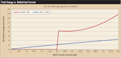
Figure 1 shows the relationship between arc flash energy and bolted fault capacity. Note that this relationship is quite linear for the IEEE 1584 equations and somewhat logarithmic for the NFPA 70E equations. Further examination also indicates that over the range of valid values (above 16kA for NFPA 70E), the IEEE 1584 method is calculated more aggressively, and the NFPA 70E method is more conservative.
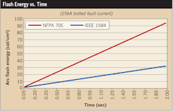
Figure 2 shows the relationship between arc flash energy and the duration of the arcing event, which is linear for both methods of calculation. However, it should be noted that the IEEE 1584 method is once again more aggressive than its NFPA 70E counterpart.
It's important to note that when using either set of equations, the “working distance” is considered to be fixed, based upon the voltage and type of equipment on which the technician will be working. Therefore, the dependent variables will be the available short-circuit current and the duration of the arc. The short-circuit current will be determined by the configuration of the electrical system, and the fault duration will be determined by the trip properties and settings of the upstream protective device. However, it's usually assumed that the outer limit for the arcing time is no more than 2 seconds. Although this is not a hard and fast rule, it accounts for the likelihood that the arcing material in an arcing field will likely be either burned off or expelled by the force of the blast. In any case, this would extinguish the arc event.
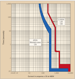
Figure 3 shows typical trip characteristics for a 400A, molded-case circuit breaker and a 2,000A, LSI solid-state breaker. Inspection of these trip characteristics shows that for certain regions of the curve, where the short-time region meets the instantaneous region, for example, there are great swings in the operating time of the circuit breakers. This point is at approximately 16kA for the 2,000A breaker and 2.8kA for the 400A breaker.
Figure 4 shows the calculated arc flash energy for the 2,000A breaker, using both IEEE 1584 and NFPA 70E calculation methods. As you can see from the graph, the available arc flash energy peaks at two points: 7.5kA and 16kA. As you might expect, these points coordinate with the “break” points of the trip curve where there is transition from the long-time to short-time trip region and at the transition from the instantaneous to short-time trip region. These peaks are not replicated on the NFPA 70E curve because that equation is not valid in the associated trip range for the 2,000A breaker. However, where larger currents are used, these peaks will occur using the NFPA 70E equation as well.
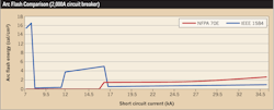
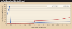
Figure 5 shows the calculated arc flash energy for the 400A breaker, using both IEEE 1584 and NFPA 70E calculation methods. For this size of breaker, the NFPA 70E equation results are nearly useless, as the NFPA 70E equation becomes valid at 16kA (40 times the trip rating of the breaker). However, the IEEE 1584 results indicate a large spike at 3kA, which is in the area of transition between the instantaneous and short-time trip regions.
Based on these figures, it's clear that calculating arc flash energy does not necessarily mesh with the “conservative” approach of calculating the worst possible case of short-circuit capacity (i.e., the highest value of short-circuit capacity). In many cases, a lower short-circuit capacity may produce a much larger arc flash energy level. For this reason, IEEE recommends that the arc flash energy be calculated both at the calculated arcing current and again at 85% of the arcing current (also known as the second-arcing current) — and that the higher arc flash energy value be used. Note that the arcing current is based upon the bolted-fault available short-circuit capacity, and is calculated for systems below 1kV as:
log [Ia] = K + 0.662 log [Ibf] + 0.0966 V + 0.000526 G + 0.5588 V log [Ibf] 0.00304 G log [Ibf] Or for systems over 1kV as: log [Ia] = 0.00402 + 0.983 log [Ibf]
Where K is a constant, V is the voltage of the system, G is the air gap between the conductors, and Ibf is the bolted-fault available short-circuit capacity.
After calculating the arc flash energy level, an appropriate selection of PPE is made using Table130.7(C)(11) from Table NFPA 70E.
What are the “tables” in NFPA 70E?
In addition to using the calculated methods for determining the arc flash energy and required personal protective equipment (PPE) described above, there is a third method of determining what type of protection to use when working on live equipment. This method is the direct application of Table 130.7(C)(9)(a) from NFPA 70E. This table is intended to be a conservative application of the principles of Annex D, without the need for performing a complete arc flash evaluation and study. However, this table is based on several assumptions:
- For panelboards and switchboards rated 600V and less, the available fault current is 25kA, and the clearing time of the protective device is 0.03 seconds (two cycles);
- For 600V class motor control centers and other such equipment, the available fault current is 65kA, and the clearing time of the protective device is 0.03 seconds (two cycles);
- For insertion or removal of starter buckets in motor control centers as noted above, the available fault current is 65kA, and the clearing time of the protective device is 0.33 seconds (20 cycles); and/or
- For 600V class switchgear containing fused switches or power circuit breakers, the available fault current is 65kA, and the clearing time of the protective device is 1 second (60 cycles).
Although this table is a useful guide where there is no other information available, it is clear that the assumptions listed above are not necessarily applicable to the systems you may be analyzing. As such, they will often lead to overclassification of protective gear for work on a specific piece of equipment. However, it is of even more concern that there is a potential for underclassification of the protective gear recommended for work on a specific piece of equipment.
In a recent arc flash study of a facility that encompassed more than 700 pieces of equipment, it was found that in 7% of cases, the application of Table 130.7(C)(9)(a) without an appropriate system study, would lead to the use of insufficient protective gear when working on live equipment. In addition, it was found that the PPE requirements of Table 130.7(C)(9)(a) were in excess of those determined through calculation 62% of the time. Therefore, although the tables are of benefit when working at a location where there is no existing arc flash study, they are no substitute for a complete and up-to-date arc flash study.
A useful method
When computer-based arc flash evaluations are run, the calculations of the software should not be blindly accepted. In many cases, the NFPA 70E equations are applied outside of their applicable range, and the results are given with only a footnote to indicate that the calculation is “out of range” (i.e., invalid). Therefore, it is important that the software output be thoroughly reviewed and applied as is appropriate to the necessary systems.
Also, it is important that both the NFPA 70E and IEEE 1584 equations be used correctly. By using both sets of equations, a conservative set of values can be assembled. It is good practice to calculate the flash energy using both methods, and to use the valid value (where only one set of equations is valid) or to use the more conservative value (where both sets of equations are valid).
Some facility managers prefer to compare the NFPA 70E and/or IEEE 1584 calculated values to Table 130.7(C)(9)(a) from NFPA 70E and to use the most conservative flash protection equipment recommendation. However, this is not a requirement of NFPA 70E, and there is debate as to whether overprotection in the form of flash suits is appropriate, as it is cumbersome for the worker.
A consolidated procedure for performing an arc flash analysis
The following steps outline a suggested procedure for performing an arc flash analysis of a facility. Although this is not the only possible procedure, it does cover a wide range of conditions, and takes a conservative approach to the application of both IEEE 1584 and NFPA 70E equations.
- Assemble existing as-built documentation — Start by collecting all of the relevant, existing as-built documentation. Include power floor plans showing locations of electrical equipment, and single-line diagrams indicating the overcurrent protective devices and cable sizes for all relevant areas.
- Field verify existing conditions — Because conditions may have changed since the original installation, it's critical that the existing conditions be field verified to ensure that the arc flash analysis is performed using accurate breaker settings and field conditions.
- Obtain the available utility fault current (range) and X/R ratio — The serving utility should be able to provide this information. Note that the utility normally guarantees a range of short-circuit current, and that the highest arc flash energy value may occur anywhere within the range of available short-circuit current values.
- Perform a short-circuit analysis — The short-circuit analysis must be performed to obtain the available bolted-fault and arc fault currents at each point in the system.
- Perform an NFPA 70E arc flash analysis — Perform the arc flash analysis using the NFPA 70E equations and parameters.
- Perform an IEEE 1584 arc flash analysis — Perform the arc flash analysis using the IEEE 1584 equations and parameters.
- Repeat steps 4 through 6 for the entire range of possible values — The short-circuit and arc flash studies must be repeated over the entire range of valid utility fault capacities. The studies may be performed in a range of fault increments to ensure that the highest arc flash energy value is captured at each component. For example, a system that has a fault value ranging from 3,000A through 12,000A may be run in 1,000A increments.
- Repeat steps 4 through 7 for all likely operating conditions — The report must be run for all likely operating conditions for the facility, including normal operation, load shedding modes, parallel operation, tie breakers open and closed, and operating on standby power. It is important that all configurations be fully evaluated to ensure that the worst-case scenario is developed for each piece of equipment.
- Eliminate invalid data — Export the arc flash reports to spreadsheet software, and delete invalid values because they do not fall within the range of valid conditions for the equation set used (i.e. NFPA 70E values calculated from short-circuit currents that are not between 16kA and 50kA as required).
- Sort the worst-case values for each component or bus — Using a spreadsheet, the remaining valid values may be sorted and the worst-case extracted for each component within the system. This value will be considered the available arc flash energy at its associated point in the system.
- Assemble the comprehensive report — The final report should indicate the available short-circuit current used at each component, the available arc flash energy, the category of PPE required to safely work on the equipment, and which set of equations was used to determine the available energy. The report should also include the working distance used in the calculation, and the flash protection boundary (generally the threshold where the available energy exceeds 1.2 cal/cm2). In addition, any information that your specific client requires (duration of arc, closing time of breaker, equipment required for safe operation, etc.) should be included in the report.
All of this information, along with the building's single-line and short-circuit capacity diagrams, should be collected in a coherent fashion and presented to the client in a binder for their use.
This method is straightforward, and keeps the report's focus on safety. Most importantly, it reminds the engineer to evaluate his equations independently, to ensure that the report contains information that is accurate, valid, and useful. With proper preparation, arc flash analysis is a tool that can prevent needless accidents and injuries in the facility for which it is prepared — the intent of NFPA 70E's requirement.
Medich is a senior electrical project engineer at Ballinger in Philadelphia.