Do the myriad rules about grounding sometimes seem a bit too much to handle? Do grounding implementation problems sometimes leave you dazed and confused, with the correct solution seemingly a bit over your head? If so, don't feel alone.
Despite the extensive literature on grounding, some of its important concepts seem to be missing from the electrical industry's oral tradition and regular practice — and some grounding misconceptions seem to be solidly anchored in their place. Consequently, many designs and installations aren't as reliable or as safe as they could be.
But you can steer clear of the confusion if you understand the concepts behind the rules. With a better understanding, you can have more confidence that your grounding system will function as you intended.
Back to basics. The first thing to understand is that ground-fault current — like all electricity — seeks to return to its power source. This principle is what makes electrical circuits work in the first place. What's the source of ground-fault current? It doesn't originate in the earth, but at the utility transformer.
Kirchoff's Law states that current will flow in inverse proportion to the impedance of the paths presented to it. Thus, the relative impedances of the various paths determine how fault current gets back to its source.
The impedance of the path between the grounding electrode and the source is almost always significantly higher than the impedance of the path through the grounding/grounded conductor.
If you're unsure about this at your facility, measure the impedance of a copper wire from the electrode to the source and compare it with the impedance through the earth.
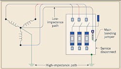
This difference in impedance means only a minute amount of fault current flows through the grounding electrode. The fault typically travels along the equipment ground (conductors and metal raceway systems), through the neutral-ground bond, and back to the source through the grounded (neutral) conductor. It's the high fault current through the low-impedance path that causes an overcurrent device to trip — not the negligible amount of current that flows through the dirt via a ground rod (Fig. 1).
If that's the case, what's the function of the grounding electrode? Believe it or not, it has several, including the following:
-
Limiting voltages imposed by lightning, surges, or accidental contact with higher voltage lines.
-
Stabilizing the voltage to earth during normal operation, helping to maintain the voltage within predictable limits.
-
Assisting the utility in clearing its own faults by basically becoming part of the utility's multi-point grounding system.
-
Providing a path to earth for static dissipation.
Ground rod spacing. Suppose you drive the first ground rod for a system. If it has a ground resistance of 25 ohms or more, 250.56 of the 2005 NEC requires you to drive a second rod. But many contractors don't bother measuring the ground resistance. They simply plan on driving two rods because doing so will meet the requirements of 250.56, regardless of actual ground resistance. Thus, two-rod installations are common, but are they necessarily correct?
The Code requires you to space rods at least 6 feet apart [250.53(B)]. However, this spacing is a minimum — and far from ideal. When using the typical 8-foot or 10-foot ground rod, you get the best results by spacing the rods at least 16 or 20 feet apart, respectively. This is much greater than the Code minimum 6-foot spacing.
Ground rods spaced less than two rod-lengths apart will interfere with each other because their effective resistance areas will overlap (Fig. 2a above). For reference, see IEEE-142 and Soares Book on Grounding. The overlap increases the net resistance of each rod, making the grounding electrode system less effective than if the rods were spaced farther apart (Fig. 2b above).
Main bonding jumper. The main bonding jumper is the link between the neutral and the equipment ground bars within the service. This vital connection allows the ground-fault current to return to the source. Without the main bonding jumper, the fault would have to travel through high-impedance earth rather than low-impedance copper. This high-impedance path would most likely limit the current and prevent circuit breakers from tripping — or at least prevent them from tripping soon enough to avoid equipment damage.
Size the main bonding jumper per Table 250.66. Many people assume this table indicates the maximum size main bonding jumper is 3/0 AWG, but that's another common misconception. The bonding jumper must be at least 12.5% of the equivalent area of the phase conductors [250.28(D)]. If you're running 11 sets of 500 kcmil conductors (a 4,000A service, for example), the main bonding jumper would need to be 700 kcmil minimum, not 3/0 AWG.
This issue is less of a concern with bonding jumpers for secondary derived systems, such as transformers and generators, since fault currents are typically much lower in those systems.
Sizing equipment grounding conductors. Designers typically use Table 250.122 when sizing equipment grounding conductors. In most cases, the size will be adequate, especially for small branch circuits. But when the available fault current is high — say 100,000A — and when an upstream circuit breaker is set to delay its trip for several cycles, you must size grounding conductors more carefully.
Metallic raceways, which typically carry more current than equipment grounding conductors, may not be installed properly or may come apart over time. Consequently, the equipment grounding conductor may be the only ground return path available. Under-sized grounding conductors may melt during a fault before they serve their purpose of providing a continuous low-impedance current path back to the source during a fault condition.
It's important to understand that conductors have withstand ratings. The Insulated Cable Engineers Association provides a standard called Short-Circuit Characteristics of Insulated Cable, number P 32-382 (1994). This standard says that for a 5-second period, a conductor's withstand rating is 1A per 42.25 circular mils.
For example, a 3/0 AWG conductor can safely carry 3,972A for 5 seconds. The I2T, 5-second withstand rating is therefore 78,883,920A. Now assume a circuit breaker is set to open in 30 cycles — a delay you might see at the service. You can quickly determine that the maximum current a 3/0 AWG can carry for 30 cycles (0.5 sec) is:
I2T = 78,883,920
I= √ (78,883,920÷T)
I= √ (78,883,920÷0.5)
I=12,560A
But if the available fault current is 65,000A or 100,000A at the load end of the grounding conductor, the grounding conductor will be quickly destroyed in the event of a fault, assuming the circuit breaker takes 30 cycles to open. You should be mindful of the available fault current and allow for the opening time of the circuit breakers, especially the main and feeder breakers in the main switchboard. Perform I2T calculations as described above, particularly when the available fault current is high. You can see that correctly sizing equipment grounding conductors isn't as simple as applying NEC minimums.
Grounding system currents. Current is present in the grounding system during normal operating conditions, not just during a fault condition. This probably explains why the Code permits ground-fault sensors to be set as high as 1,200A to prevent nuisance tripping [230.95(A)].
Other than ground faults, several things can produce current in the grounding system, including the following:
-
Induced currents from adjacent current-carrying wires.
-
Induced currents from motors (particularly single-phase).
-
Capacitive coupling between the phase and neutral wires to the grounding conductors. This phenomenon is known to cause nuisance GFCI tripping in long circuits.
-
Electrostatic discharge from equipment.
Ground loops. You can form ground loops through the interaction of power grounding and low-voltage cabling. Low-voltage cabling often contains a signal ground conductor that can essentially bond the internal signal grounds between different pieces of electronic equipment together. If an internal bond also exists between the power ground and the signal ground within the electronic equipment, current can flow through this loop. Though shielded low-voltage cables are typically grounded only at one end to prevent ground loops, a separate signal ground wire within the shield may still create a bond.
For an example of where this commonly occurs, think about a computer network and the shields on devices like printers, routers, and workstations. If you're linking different pieces of equipment together, you're interconnecting devices that have a potential between their respective ground pins (Fig. 3). If you have a complete circuit through the signal wires, you have a ground loop. Ground currents will flow because of this potential, and they'll create electrical noise that can interfere with system operation. Electromagnetic fields that pass through this loop could also cause current to flow.
To minimize this phenomenon, you must limit the potential between these various grounding points. TIA/EIA J-STD-607-A recommends a maximum potential of 1V between grounding points. Interestingly, it also recommends one large ground loop for grounding multi-story buildings (Fig. 4). In computer networks, limiting the potential between grounding points clearly takes precedence over concerns about circulating loops of ground currents. Audiovisual equipment is much more sensitive, however.
Any given building has hundreds, if not thousands of low-voltage cables, and each may form its own ground loop in combination with the power grounding system. Unfortunately, there's no practical way in a standard building to guarantee an even ground plane throughout.
The best you can do is properly ground the key pieces of equipment. This means providing ground bars in all telecommunications and audio/video rooms, and making sure every piece of equipment within these rooms is tied to these ground bars. This ensures a fairly even ground plane within the room — at least in the lower frequency range.
A commonly prescribed cure for these kinds of grounding issues is to provide equipotential ground planes over a wide range of frequencies. Methods include using ground meshes within slabs and signal reference grids beneath raised floors. Given the cost of such measures, these methods are typically reserved for the most sensitive communications facilities — not typical commercial or institutional facilities. An equipotential ground plane is only one step, though. It's not a cure-all for ground loops, because currents can always be induced by electromagnetic fields that pass through conductors.
Don't be overwhelmed by the vast amount of minutia related to grounding. Having a handle on a few basic grounding concepts should help you sort things out. Good grounding is key to the operational success of any facility, so the more informed your designs, the more reliable the installation will be and the fewer power quality issues will surface.
Janof, P.E., is an associate and senior project manager at Sparling, an electrical engineering and technology consulting firm with offices in Seattle and Portland.