Last month, we saw how you can use vectors to define complex circuits and determine current. This month, we'll show you how to use vector diagrams and some simple math to calculate neutral currents in 3-phase, 4-wire circuits.
You can graphically display phase currents in any 3-phase system with vectors originating from a common point and positioned 120° from each other. The terminology used to describe this condition is “phase displacement.” With the vector lengths (magnitudes) representing the respective phase currents, you can make a vector diagram.
If you pay close attention to the scale used (say ½ inch = 25A) and follow our previously discussed vector laws (see “The Basics of Vector Analysis — Part 1” in the August 2008 issue on page C14), you can get a complete graphical solution that shows the resulting neutral currents.
Problem No. 1 (three phases used; balanced loading)
Unfortunately, this method is sometimes cumbersome. Also, the extent of accuracy is a function of your measuring and drafting abilities. As a result, we use vectors in this instance only to provide a graphical picture of phases, relative to their respective magnitudes and directions. Normally, we insert the actual current values and the angles between them into some basic trigonometric equations to get a quick and accurate solution. Nevertheless, creating a vector diagram is an important part of this procedure. Let's do some sample problems to see how this works.
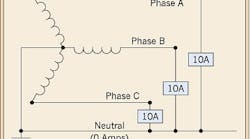
Looking at Fig. 1, you can see that Phases A, B, and C are each equally loaded with a 10A phase-to-neutral load. Now, let's begin the vector analysis process. First, we create a vector diagram, as shown in Fig. 2, with the phase current Vectors A, B, and C positioned 120° apart.
Next, we create a parallelogram by drawing dotted lines parallel (and of equal lengths) to Vectors A and B. Using the parallelogram rule discussed in Part 1 of this series, we draw Vector N, which is the result of vectorally adding Vectors A and B. Because Vectors A and B have the same magnitude, Vector N creates two equilateral triangles within the parallelogram. And because the sides of an equilateral triangle are equal in length, the magnitude of Vector N must also be 10A.
Looking at Fig. 2 again, you can see that Vector N is in a direction 180° opposed to Vector C, which represents the current flowing on Phase C. From one of the other basic vector laws discussed in Part 1, the resultant magnitude of the diametrically opposed vectors is the difference between their values. In this case, 10A-10A = 0.
Problem No. 2 (two phases used; balanced loads)
If we create similar parallelograms at Vectors A and C, and B and C, and then draw similar N vectors, we'll get the same cancellation. This proves that in a 3-phase, 4-wire grounded wye system, the 60-Hz current flowing in the neutral conductor is 0 when all phase currents are equal.
Now let's suppose Phases A and B are equally loaded with 10A phase-to-neutral loads, while Phase C current varies from 0 to 10A. The vector diagram for this condition (Fig. 3) shows that a portion of the neutral conductor current, as represented by Vector N, results from the vector addition of Vectors A and B. As we've previously seen, its magnitude is 10A. If the Phase C current is 10A, we know from Problem 1 that the total neutral current is 0. But what if the Phase C current varies? What would be the respective neutral currents?
Again referring back to Problem 1, we see that the difference between varying Phase C current vectors and the magnitude of Vector N (10A) will result in varying neutral currents. For example, if the magnitude of Vector C is 2A, then the neutral is 8A; if Vector C is 4A, then the neutral current is 6A, and so forth.


