Harmonics and certain fuses can make for a destructive mix. Mark McGranaghan, vice president of consulting services for EPRI-PEAC, examines how to keep them apart. And John DeDad, EC&M's editorial director, has some sound advice on silencing electrical noise.
Q. We have a shunt capacitor bank on the utility side of a customer load that includes variable speed drives. The bank is 700 kVAR per phase on a 7.2/12.5kV grounded-wye system. The capacitors are protected with current limiting (CL) fuses in series with expulsion fuses. The CL fuses have been blowing at random. We'll replace a fuse and have no problems for a week or two, but then it or one on an adjacent phase will blow again. The capacitors were installed to compensate for the low power factor of the customer's load. These CL fuses are nearly $200 each. We've tried to ground the wye point or float it, but it doesn't seem to make a difference. We also thought maybe the customer or someone else was generating harmonics, but there was no evidence of their presence. We think we'll need to install recording instrumentation to capture the event associated with fuse blowing.
McGranaghan's answer: Your initial response that this could be harmonics is probably correct. CL fuses can sometimes be sensitive to harmonic levels, and the sensitivity level may depend on the specific harmonic components involved.
Depending on the capacitor location, it may be possible to measure the harmonic currents in the feeder phase currents at the substation to get an idea of any harmonic loading. If the capacitors are part of a resonant circuit that's magnifying harmonic currents, these currents will also appear in the feeder currents in the substation.
As a worst-case assumption, you could presume that essentially the entire harmonic component at the resonance frequency that you measure at the substation is also appearing in the capacitor bank.
As an alternative, you can take measurements at the capacitor bank location of the primary phase currents using a hot stick current transformer and a good quality handheld harmonics analyzer.
With harmonic currents, the total capacitor rms current may be less than the fuse rating and still cause nuisance fuse blowing. This is especially true if you're fusing at 135% of capacitor-rated current. If you have high current distortion, you may also have voltage distortion issues.
At the very least, take measurements at the substation to evaluate any voltage distortion concerns. Make sure these measurements cover the range of possible capacitor configurations on the feeders out of the substation. The resonance will be related to the total capacitance in service on all the feeders.
Q. We're experiencing problems that I'm told are caused by electrical noise. What causes electrical noise and what can be done to eliminate it?
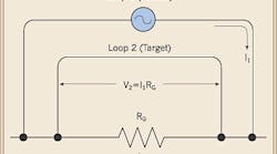
DeDad's answer: Electrical noise can be caused by ground loops, which occur most often in circuit returns (Fig. 1 on page 24). Another cause is capacitive coupling, where the noise is capacitively picked up mostly in high-impedance circuits. Inductive coupling can also be a culprit, where a changing magnetic field is created around a wire carrying alternating current. The noise is transferred through air to another wire close by (Fig. 2 on page 24).
You can't completely eliminate electrical noise but you can reduce it to “tolerable” levels. Basically, each practical noise-reduction action you take will result in less noise. Some viable noise-reduction strategies include the following:
-
Reducing the amplitude of the noise by raising the impedance to it in the harmful direction.
-
Shunting the noise away by lowering the impedance to it in a benign direction.
-
Breaking the link between the noise and the affected circuit.
Other acceptable noise-reduction steps include the following:
-
Meeting or exceeding grounding conductor sizing so that a lowering of impedance will help shunt noise away from affected equipment.
-
Separating power and instrumentation/control loads so that they're fed from different power panels.
-
Using isolation transformers in place of standard transformers to step down voltages to required levels.
-
Using shielded power-line filters at control cabinets and rack plugstrips to prevent noise on the power line.
Got PQ problems? Send your questions to [email protected].


