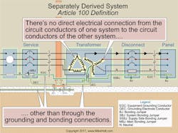
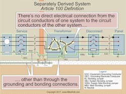
A transformer transfers electrical energy from one system to another by induction. Except for grounding and bonding connections, there’s no physical connection between the two systems. For this reason, the NEC refers to transformers as “separately derived systems,” as shown in Fig. 1.
The ratio of the number of turns in the primary (supply) side to the number on the secondary (load) side determines how much the unit transforms the power supplied to it. This is a key concept in transformer theory and application.
Related
Typically, a transformer raises or lowers the voltage. But isolation transformers don’t; they simply decouple two systems. Let’s cover some transformer basics before addressing NEC requirements.
Wye vs. delta
Wye-configured transformers have one lead from each of three windings connected to a common point. The other leads from each of the windings are connected to the line conductors. A wye-configured secondary is often represented with a Y-shaped arrangement of the windings.
Delta-connected transformers have three transformer windings connected end-to-end with each other. The line conductors are connected to each point where two windings meet. This system is called a “delta” because when drawn it looks like a triangle (the Greek letter delta).
High-leg conductor identification [110.15]
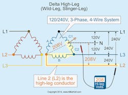
The terms “high-leg,” “wild-leg,” or “stinger-leg” are used to identify the conductor of a delta-connected system that has a nominal voltage rating of 208V to ground. The high-leg voltage is the vector sum of the voltage of transformers A and C1, or transformers B and C2, which equal (240V ÷ 2) × 1.732 = 208V for a 120/240V secondary (Fig. 2).
If the actual voltage of the delta-connected system isn’t 120/240V on the secondary, the actual high-leg voltage would = (line voltage ÷ 2) × 1.732. For example, what’s the actual voltage of the high-leg if the delta-configured secondary is 115/230V, 3-phase?
High-leg voltage = (line voltage ÷ 2) × 1.732
High-leg voltage = (230V ÷ 2) × 1.732 = 199.18V
On a 4-wire, delta-connected, 3-phase system, where the midpoint of one phase winding is grounded (high-leg system), the conductor with 208V to ground must be durably and permanently marked by an outer finish orange in color or other effective means. Such identification must be placed at each point on the system where a connection is made if the neutral conductor is present [110.15 and 230.56].
When replacing equipment in existing facilities that contain a high-leg conductor, ensure the high-leg conductor is replaced in its original location. Prior to 1975, the high-leg conductor was required to terminate on the “C” phase of panelboards and switchboards. Failure to re-terminate the high-leg as it was in the existing installation can result in 120V circuits inadvertently connected to the 208V high-leg, with disastrous results.
Rating, voltage, current
Transformers are rated in kilovolt-amperes (kVA); 1 kVA = 1,000 volt-amperes (VA). The voltage measured on the circuit conductors that supply the primary side is the primary line voltage. The voltage measured on the secondary side circuit conductors that feed the load is the secondary line voltage. The single-phase formula for calculating the line current of a transformer is: I = VA ÷ E. For 3-phase, I = VA ÷ (E × 1.732). Convert kVA to VA by multiplying kVA × 1,000.
With this background, you can more readily make sense of the NEC requirements for transformers.
Conductor identification
Where the premises wiring system contains feeders supplied from more than one voltage system, each ungrounded conductor (at all termination, connection, and splice points) must be identified by phase or by line and system [215.12(C)]. Identification can be by color coding, marking tape, tagging, or other means approved by the authority having jurisdiction. The identification must be documented in a manner that’s readily available, or it must be permanently posted at each panelboard [215.12(C)(1)(a) and (b)]. Conductors with insulation that’s green (or green with one or more yellow stripes) can’t be used for an ungrounded or neutral conductor [250.119].
Overcurrent protection device (OCPD)
To protect the windings of a transformer against overcurrent, use the percentages listed in Table 450.3(B) and its applicable notes. Article 450 is for the protection of the transformer windings, not the conductors supplying the transformer or leaving it. Where 125% of the primary current doesn’t correspond to a standard fuse or nonadjustable OCPD, you can use the next higher rating, as listed in Sec. 240.6(A), but only for currents of 9A or more.
Primary conductor sizing
Size primary conductors at least 125% of the continuous loads, plus 100% of the noncontinuous loads, based on the terminal temperature rating ampacities as listed in Table 310.15(B)(16), before any ampacity adjustment [210.19(A)(1)].
You must protect the conductors against overcurrent after ampacity adjustment, as specified in Sec. 310.15 [240.4]. You can use the next higher standard rating of OCPD (above the ampacity of the conductors being protected) if the OCPD rating doesn’t exceed 800A [240.4(B)].
Let’s run through an example problem to clarify these points.
What size primary conductor can be used for a 45kVA continuous loaded, three-phase, 480V transformer, where the primary OCPD is sized at 70A?
Step 1: Size the primary conductor at 125% of the primary current rating.
I = 45,000VA ÷ (480V × 1.732) = 54A
54A × 1.25 = 68A
A quick check of Table 310.15(B)(16) reveals that a 4 AWG conductor is rated 70A at 60°C [110.14(C)(1)(a)(1)].
Step 2: Verify the conductors are protected per their ampacities [240.4]. A conductor rated 70A at 60°C can be protected by a 70A primary OCPD.
Secondary conductor sizing
The ampacity of the secondary conductor must be at least the rating of the device supplied by the secondary conductors or the OCPD at the termination of the secondary conductors [240.21(C)(2)]. Assume the secondary conductors are intended to carry the full capacity of the transformer continuously.
Step 1: Determine the rating of the device supplied by the secondary conductors at 125% of the secondary rating [215.2(A)(1)(a)].
Step 2: Size the secondary conductors so their ampacity is at least that of the device they supply [240.21(C)].
Again, let’s run through an example problem to clarify these points.
What size secondary conductor can be used for a 45kVA continuous loaded, 3-phase, 480-120/208V transformer? (Fig. 3)
Step 1: Determine the secondary current rating.
Secondary current = transformer VA ÷ (secondary voltage × 1.732)
Secondary current = 45kVA ÷ (208V × 1.732) = 125A
Step 2: Size the secondary OCPD for a continuous loading (125% of the secondary current rating) [215.3].
125A × 1.25 = 156A
In this case, we’ll choose a 175A OCPD device [240.6(A)].
Step 3: Size the secondary conductor so it has an ampacity at least that of the 175A secondary OCPD (from Step 2) [240.21(C)(2)].
Conductor rated 175A at 75°C [Table 310.15(B)(16), 110.14(C)(1)(b)(1)]
Grounding and bonding
You must install a system bonding jumper at the same location where the grounding electrode conductor (GEC) terminates to the neutral point of a transformer. Size it per Sec. 250.102(C), based on the area of the secondary conductors [250.30(A)(1) and 250.28(D)(1)].
A GEC must connect the neutral point of a separately derived system to a grounding electrode of a type identified in Sec. 250.30(A)(4). Size the GEC per 250.66 based on the area of the ungrounded secondary conductor [250.30(A)(5)].
Can you be error-free? If you think of transformers as being the electricity that goes through them, it’s easier to apply transformer theory. Except for autotransformers, all transformers consist of two sets of interacting coils. The turns ratio of the primary set to the secondary set determines the degree to which the voltage is transformed (raised or lowered).
To keep from making grounding and bonding errors, remember there’s a difference between grounding and bonding. Grounding is the connection to the earth. It’s accomplished with the grounding electrode and the GEC. This connection to earth won’t provide an effective ground fault return path. That’s the role of proper bonding.
With transformers, a vital link in the bonding path is the system bonding jumper. It must be installed on the secondary of the transformer, either in the transformer or in the panel. The system bonding jumper completes the bonding path back to the source (the transformer secondary) to provide an effective fault current path.
Holt is the owner of Mike Holt Enterprises, Inc. in Leesburg, Fla. He can be reached at www.mikeholt.com.
About the Author

Mike Holt
Mike Holt is the owner of Mike Holt Enterprises (www.MikeHolt.com), one of the largest electrical publishers in the United States. He earned a master's degree in the Business Administration Program (MBA) from the University of Miami. He earned his reputation as a National Electrical Code (NEC) expert by working his way up through the electrical trade. Formally a construction editor for two different trade publications, Mike started his career as an apprentice electrician and eventually became a master electrician, an electrical inspector, a contractor, and an educator. Mike has taught more than 1,000 classes on 30 different electrical-related subjects — ranging from alarm installations to exam preparation and voltage drop calculations. He continues to produce seminars, videos, books, and online training for the trade as well as contribute monthly Code content to EC&M magazine.


