Thank you for visiting one of our most popular classic articles. If you are seeking more updated information on this topic, please read one of our more recent pieces, NEC Requirements for Sizing Junction Boxes and Pull Boxes, by Mike Holt. |
Note: This article is based on the 2005 NEC.
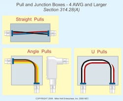
The sizing requirements for pull boxes, junction boxes, handhole enclosures, and conduit bodies exist to prevent conductor insulation damage. Those requirements are in 314.28, and they apply to all conductors 4 AWG and larger (Fig. 1). To illustrate how these requirements prevent conductor insulation damage, let's consider two extremes in a straight pull situation.
Now, suppose you have those same two raceways mounted on a 4-foot box. Obviously, you have plenty of space, and you won't need to make severe bends in the conductors. Because you don't have the luxury of installing 4-foot boxes for every wire pull you do, you need to calculate the box size you really need.
The scenario we just discussed is a straight pull, one in which the conductor enters the box on one side and exits on the other — but not at an angle and not with any splices. It's a “straight-through” installation. The NEC addresses these separately from other types of pulls.
Straight pulls
Why would you install a pull box for a straight pull? Why break the raceway with a box at all? One reason is a very long conductor run; another is to restart the 360° bend limitation of the applicable raceway article. The pull box provides another lubrication point, plus it allows you to reduce the force needed to pull that run in the first place.
For straight pulls, 314.28(A)(1) requires that the length of the box be at least eight times the trade size of the largest raceway. To correctly apply 314.28(A)(1), just multiply the largest raceway size by eight. The box must be at least as long as that number.
Angle pulls, u-pulls, and splices
Of course, junction boxes are used for reasons other than simply making a straight pull easier. You may use a junction box to splice conductors, combine runs from multiple raceways into one raceway, split runs from one raceway into multiple raceways, or simply to change the direction of the raceways. In such situations, junction box sizing requirements are a bit more complicated. Start with the largest raceway size like you did in the straight pull, but also do the following:
- Multiply the raceway size by six, rather than eight.
- Add together the sizes of any other raceways on the same wall and row.
- Add the results of step 1 and step 2.
- The length of the box must be at least the number you came up with in step 3.
When conductors come into a junction box in one raceway and exit the box in another raceway (not a straight pull) of a different size, how much distance do you need between those raceways? You need six times the trade size of the larger raceway. Measure that distance from the nearest edge of one to the nearest edge the other — not center to center.
Removable covers
When conductors enter an enclosure with a removable cover (e.g., conduit body, handhole enclosure, or wireway), the distance from the removable cover to where the conductors enter must not be less than the bending distance listed in Table 312.6(A), based on one conductor per terminal.
Pull box sizing (Example 1)
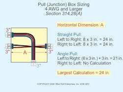
Let's say a junction box contains two trade size 3 raceways on the left side and one trade size 3 raceway on the right side. The conductors from one of the trade size 3 raceways on the left wall are pulled through a trade size 3 raceway on the right wall (straight pull). The conductors from the other trade size 3 raceways on the left wall are pulled through a single trade size 3 raceway at the bottom of the pull box (angle pull). If it sounds confusing, draw it on paper.
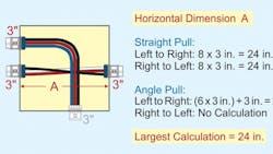
What is the horizontal dimension of this box? See Fig. 3.
Left to right straight pull 8 × 3 inches = 24 inches
Right to left straight pull 8 × 3 inches = 24 inches
Left to right angle pull (6 × 3 inches) + 3 inches = 21 inches
Right to left angle pull - no calculation
Answer: 24 inches [314.28]
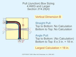
What is the vertical dimension of this box? See Fig. 4.
Top to bottom straight - no calculation
Bottom to top straight - no calculation
Top to bottom angle - no calculation
Bottom to top angle 6 × 3 inches = 18 inches
Answer: 18 inches [314.28]
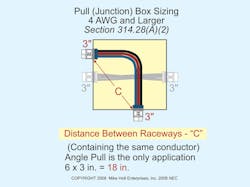
What is the minimum distance between the two trade size 3 raceways that contain the same conductors? See Fig. 5.
6 × 3 in. = 18 inches
Answer: 18 inches [314.28]
Pull box sizing (Example 2)
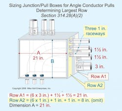
Let's say a pull box contains a trade size 2 and trade size 3 raceway on the left side, a trade size 3 raceway on the top, and a trade size 2 raceway on the right side. The trade size 2 raceways are a straight pull, and the trade size 3 raceways are an angle pull. Again, you have to determine three numbers, so you'll probably want to draw this on paper.
What is the horizontal dimension of the box?
Left to right straight pull 8 × 2 inches = 16 inches
Right to left straight pull 8 × 2 inches = 16 inches
Left to right angle pull (6 × 3 inches) + 2 inches = 20 inches
Right to left angle pull - no calculation
Answer: 20 inches [314.28(A)(2)]
What is the vertical dimension of the box?
Top to bottom straight - no calculation
Bottom to top straight - no calculation
Top to bottom angle 6 × 3 inches = 18 inches
Bottom to top angle - no calculation
Answer: 18 inches [314.28(A)(2)]
If the two trade size 3 raceways contain the same conductors, what is the minimum distance between these raceways?
6 × 3 inches = 18 inches
Answer: 18 inches [314.28(A)(2)]
Avoiding errors
How can you prevent junction box and handhole enclosure sizing errors on your electrical projects? One of the most common mistakes is to calculate for the wrong wall of the box. To avoid that particular mistake, draw out the problem so you can see what you're doing instead of having to juggle things around in your head.
Before your next project arrives with a deadline that's ridiculous — but must be met anyhow — become a junction box sizing whiz by practicing. If you don't have a previous job to use as practice, then create your own practice exercises. Use Examples 1 and 2 again, but just change the numbers. Each time you do one, you'll get a little faster. Then when you need to quickly and correctly size your junction boxes, you'll be completely up to speed.
Sidebar: Sizing Steps
Step 1: Always draw out the problem.
Step 2: Calculate the horizontal distance(s):
- Left to right straight calculation
- Right to left straight calculation
- Left to right angle or U pull calculation
- Right to left angle or U pull calculation
Step 3: Calculate the vertical distance(s):
- Top to bottom straight calculation
- Bottom to top straight calculation
- Top to bottom angle or U pull calculation
- Bottom to top angle or U pull calculation
Step 4: Calculate the distance between raceways enclosing the same conductors.
For more information, read "NEC Requirements for Sizing Junction Boxes and Pull Boxes."
About the Author

Mike Holt
Mike Holt is the owner of Mike Holt Enterprises (www.MikeHolt.com), one of the largest electrical publishers in the United States. He earned a master's degree in the Business Administration Program (MBA) from the University of Miami. He earned his reputation as a National Electrical Code (NEC) expert by working his way up through the electrical trade. Formally a construction editor for two different trade publications, Mike started his career as an apprentice electrician and eventually became a master electrician, an electrical inspector, a contractor, and an educator. Mike has taught more than 1,000 classes on 30 different electrical-related subjects — ranging from alarm installations to exam preparation and voltage drop calculations. He continues to produce seminars, videos, books, and online training for the trade as well as contribute monthly Code content to EC&M magazine.
