Preventing Fires at the Gas Pump
Mixing flammable liquids and gas with improper wiring can create the potential for a dangerous situation.
Imagine how terrible it would be if you were pumping gas in your company truck or car and the gas dispensing station erupted into a ball of fire. Although it rarely happens, there are documented cases of this occurring across the country. A primary goal of the requirements of Art. 514, Motor Fuel Dispensing Facilities, is to prevent just such a situation from happening.
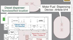
A key question that arises in applying the requirements of Art. 514 is, What is a motor fuel dispensing facility? Sec. 514.2 defines it as a location where gasoline or other volatile flammable liquids or liquefied flammable gases are transferred to the fuel tanks or auxiliary fuel tanks of self-propelled vehicles, such as passenger vehicles and utility trucks, or approved containers (Fig. 1). However, the entire facility isn't subject to the rules of Art. 514 just because it's equipped with a fuel dispensing station. The FPN under 514.2 explains what you need to do about the other areas within the facility.
Diesel fuel is considered combustible, not flammable. Therefore, a diesel dispensing area is unclassified, and associated electrical equipment and wiring need not comply with the requirements of Chapter 5. But it's common to wire diesel fuel dispensers adjacent to gasoline dispensers. If conduit for the diesel dispenser passes through the Class I, Div. 1 or 2 areas around the gasoline dispenser, the wiring methods and sealing requirements in Art. 501 apply (Fig. 2).
There are several other rules to bear in mind when determining if a motor fuel dispensing facility is classified:
-
You must apply Table 514.3(B)(1) to delineate and classify motor fuel dispensing facilities.
-
A Class I, Div. 1 or 2 area doesn't extend beyond an unpierced wall, roof, or other solid barrier [514.3(B)(1)].
-
Raceways installed underground below a Class I, Div. 1 or 2 location are considered to be in a Class I, Div. 1 location to the point of emergence above grade (514.8).
-
Sales or storage rooms are unclassified if these rooms don't open to a Class I, Div. 1 location. However, they're considered Class I, Div. 1 if they open to a Class I, Div. 1 location.
When you install electric equipment and wiring within a Class I, Div. 1 or 2 location, as defined in Table 514.3(B)(1), you must do so per the installation requirements in Chapters 1 through 4 and Art. 500 and 501. For this reason, you must use threaded rigid metal conduit (RMC) or threaded intermediate metallic conduit (IMC) for fixed wiring. But if you're installing the wiring underground, you can use rigid nonmetallic conduit (RNC), in accordance with 514.8.
Per 514.7, you must install wiring above a Class I, Div. 1 or 2 location, as defined in Table 514.3(B)(1), in a raceway or inside a cable that meets the requirements of 511.7(A)(1). Fixed lighting above travel lanes or exposed to physical damage must be located at least 12 ft above floor level unless the luminaire is totally enclosed or constructed to prevent sparks or hot metal particles from escaping [511.7(B)] (Fig. 3).
Electrical wiring installed underground, below the surface of a Class I, Div. 1 or 2 location, as defined in Table 514.3(B)(1), is Class I, Division 1 to the point of emergence above grade (514.8). You must install underground wiring in threaded RMC or IMC, but you can use RNC underground below a Class I, Div. 1 or 2 location if the raceway is buried under at least 2 ft of cover. Otherwise, you have to use threaded RMC or IMC for the last 2 ft of the underground run to emergence, or to the point of connection to an aboveground raceway (Fig. 4).
The raceway seal carries its own set of requirements, depending on its location (514.9):
-
You must install a listed raceway seal in each conduit run entering or leaving a dispenser. It has to be the first fitting after the conduit emerges from the earth or concrete.
-
You must install a listed raceway seal in each conduit run that leaves a Class I, Div. 1 or 2 location [501.5(A)(4) or 501.5(B)(2)]. The NEC doesn't allow you to use unions, couplings, boxes, or fittings other than explosionproof reducers between the seal fitting and the point where the conduit leaves the Class I area (Fig. 5).
The raceway seal must be accessible and can't contain splices [501.5(C)]. The total conductor area can't exceed 25% of the cross-sectional area of rigid metal conduit unless the seal fitting is approved for 40% fill.
Disconnects and controls.
Disconnects for dispensing stations need to allow for rapid response to hose breakage or other events that creates a fuel-related fire or explosion hazard (514.11):
-
Each circuit leading to or through a dispenser, including equipment for remote pumping systems, must have a clearly identified and readily accessible switch located remote from the dispenser to disconnect simultaneously all conductors of the circuit, including the grounded neutral conductor. You can't use single-pole breakers with handle ties.
-
The dispenser disconnect at an attended self-service station must be located no more than 100 ft from the dispenser and at a location acceptable to the AHJ.
-
The dispenser disconnect at an unattended self-service station must be located more than 20 ft and less than 100 ft from the dispensers and at a location acceptable to the AHJ. You must install additional emergency controls on each group of dispensers or the outdoor equipment used to control the dispensers to shut off all power to all dispensing equipment at the station.
Remote pump control wiring for dispensers must be isolated to prevent electrical feedback. This means dispenser pump control wiring can't supply more than one dispenser because it could cause electrical feedback when another dispenser is in operation (514.13).
Grounding.
The goal of grounding is to eliminate the potential for current flow between metal objects or between metal objects and ground and to prevent flashovers and arcing.
You must bond all raceway terminations between the hazardous classified location and the service or separately derived system disconnect to the enclosure (514.16). It's acceptable to use a threaded conduit entry, bushing jumper, or bonding locknut. You can't use a locknut or double locknut as the means of bonding of the raceway terminations [501.16(A)].
You can use setscrew and compression couplings and connectors for electrical metallic tubing, IMC, or RMC installed in an unclassified area, provided the circuit doesn't pass through, or is part of, any circuit within a hazardous classified location.
A key purpose of the requirements of Art. 514 is to prevent undesired or catastrophic ignition of flammable gases or liquids at fuel dispensing stations. By following its requirements, you're isolating ignition sources through proper sealing and preventing sparks through proper grounding. You're also providing for a safe, fast, and reliable means of interrupting power to the dispensing station if the unthinkable happens.
Are you still confused by the Code? For additional information on Code-related topics please visit www.mikeholt.com or send an e-mail directly to the author at [email protected].


