One of the principal NEC requirements for circuit protection is that you shut down the equipment rather than let supply conductors melt from overload. This can cause confusion, however, because Art. 695 seems to require just the opposite.
A fire pump supplies water to a facility's fire protection piping, which, in turn, supplies water to the sprinkler system and fire hoses. Obviously, it's vital to keep that supply of water flowing. The core principle of Art. 695 is the fire pump motor must run no matter what — because it exists solely to protect the facility and people who work there. So keeping that fire pump running is mandatory, regardless of the consequences to the pump or its circuits. Saving the fire pump or its conductors is a hollow victory if you lose personnel and/or the facility.

Art. 695 is “backward” from the rest of the NEC because it won't shut down equipment in the event of an overload. Yet, many of its requirements are obvious. For example, you have to install the fire pump wiring in a location that minimizes its exposure to fire. As you read through Art. 695, several requirements will jump out as being common sense. In addition to these NEC requirements, you will also find many requirements in other NFPA standards, such as NFPA 20 Standard for the Installation of Stationary Pumps for Fire Protection. These rules include the physical location of the fire pump, which must also be in a location that minimizes its exposure to fire.
Nevertheless, some requirements will initially seem wrong — until you go back to that core principle of “run no matter what.” For example, the disconnect must be lockable in the closed position [695.4(B)(2)(2)]. You would expect a normal disconnect to be lockable in the open position — so you can de-energize the circuit and keep it that way. But fire pump disconnects are not normal. You lock them closed to prevent de-energization of the circuit.

Power sources [695.3]. You must supply power to fire pump motors from a reliable source that has the capacity to carry the locked-rotor current of the fire pump motor(s) and pressure maintenance pump motors. This source must also be capable of supplying the full-load current of any associated fire pump equipment. Reliable sources of power include single sources such as:
-
A separate electric utility service from a connection located ahead of (but not within) the service disconnecting means.
-
An on-site power supply, such as a generator. This can supply a fire pump only if it's located (and protected) to minimize damage by fire.
If a single source isn't adequate, you can use a combination of sources. The Authority Having Jurisdiction (AHJ) has final say as to what constitutes a reliable source of power.
You must also ensure power continuity, by protecting supply circuits from inadvertent disconnection [695.4]. To do this, you can use a direct connection or a supervised connection.
Direct connection. The supply conductors must directly connect the power source either to a listed fire pump controller or to a listed combination fire pump controller and power transfer switch [NFPA 20:9.3.2.2.2].
Supervised connection. You can install a single disconnecting means and associated overcurrent protective device(s) (OCPD) between a remote power source and one of the following:
-
A listed fire pump controller.
-
A listed fire pump power transfer switch.
-
A listed combination fire pump controller and power transfer switch.
Size the supply transformer for no less than 125% of the sum of the fire pump and pressure maintenance pump(s) motor loads, and 100% of the ampere rating of the accessory equipment [695.5].
Disconnects [695.4(B)]. The disconnecting means must:
-
Be identified as suitable for use as service equipment.
-
Be lockable in the closed position.
-
Not be located within equipment that feeds loads other than the fire pump.
-
Be located sufficiently remote from other building or other fire pump source disconnecting means.
-
Be marked “Fire Pump Disconnecting Means.” The letters must be at least 1 inch in height and be visible without opening enclosure doors or covers.
Power wiring [695.6]. You must route the supply conductors outside buildings, where possible. In situations where that's not possible, encase them in 2 inches of concrete or brick [230.6(2)]. In either case, install these conductors as service entrance conductors per Art. 230 [695.6].
Fire pump supply conductors on the load side of the final disconnect [695.6(B)] must be independent of all other wiring. You can route them through a building only if using one of the methods specified in 695.6(B).
If conductors supply fire pump motors or accessory equipment, size them no less than 125% of the sum of the motor full-load current as listed in Table 430.248 (or 430.250) plus 100% of the ampere rating of the accessory equipment [695.6(C)].
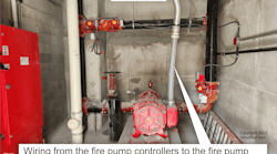
Conductors supplying a single fire pump motor must be sized per 430.22. This means the branch-circuit conductors to a single fire pump motor must have an ampere rating of not less than 125% of the fire pump motor full-load current (FLC) — as listed in Table 430.248 or 430.250. You can run wiring from the fire pump controller to the fire pump motor only in raceway listed in 695.6(E), and you cannot use ground-fault protection for fire pumps [695.6(H)].
Overcurrent protection [695.6(D)]. Overcurrent protection devices (OCPDs) must be sized to carry the sum of the locked-rotor current of the fire pump and pressure maintenance pump motor(s) indefinitely, and 100% of the ampere rating of the fire pump's accessory equipment.
Why such big OCPDs? To protect fire pump branch-circuit and feeder conductors against short circuits — not overloads. Again, the fire pump must run no matter what — so Art. 695 expressly forbids automatic overload protection. Isn't this risky? Not really. By design, you have overload prevention built in. These circuits have a dedicated load and supply, with installation requirements that greatly minimize the chance of overload.
But wouldn't short-circuit protection shut the pump down and thus violate the “run no matter what” rule? Yes and no. A short circuit would shut down the pump anyhow. Short-circuit protection makes it possible to fix the short circuit and then run the pump.
The requirement to carry the locked-rotor currents indefinitely applies to OCPDs in the fire pump circuit(s), not to other conductors or devices.

Voltage drop [695.7]. The voltage at the line terminals of the controller, when the motor starts (locked-rotor current), must not drop more than 15% below the controller's rated voltage. Also, the voltage at the motor terminals must not drop more than 5% below the voltage rating of the motor when the motor operates at 115% of the fire pump full-load current rating.
Now it's time to test your knowledge with this problem. A 25-hp, 208V 3-phase fire pump motor is 175 feet from the service. The fire pump motor controller is 150 feet from the service. What size conductor must you install to the fire pump motor controller? Equipment terminals are rated 75°C (Fig. 1).
Rearrange the basic voltage drop formula for a 3-phase system into this new formula:
Cmil=(1.732×K×I×D)÷VD
Use the following values when making your calculation.
K=12.9 ohms, copper
I=404A (locked-rotor, Table 430.251B)
D=150 feet
VD=31.2V (208V×15%)
Plug these values into the formula and reference the appropriate NEC table to obtain your answer.
Cmil=(1.732×12.9 ohms × 404A × 150 ft) ÷ 31.2V
Cmil=43,397
As per Chapter 9, Table 8 of the NEC this particular arrangement calls for a 3 AWG conductor.
Where you increase the size of ungrounded conductors, you must proportionately increase equipment-grounding (bonding) conductors (where installed) — according to the circular mil area of the ungrounded conductors [250.122(B)].
Now, for the same pump, what size conductor must you install to the fire pump motor? Remember, it's 25 feet from the controller (Fig. 2).
The operating voltage at the terminals of the motor must not drop more than 5% below the voltage rating of the motor while the motor is operating at 115% of the full-load current rating of the motor.
Cmil=(1.732×K×I×D)÷VD
K=12.9 ohms, copper
I=86A (74.8A at 115%), Table 430.250
D=175 feet
VD=10.4V (208V×5%)
Cmil=(1.732×12.9 ohms×86A×175 ft)÷10.4V
Cmil=32,332
As per Chapter 9, Table 8 of the NEC, this particular arrangement calls for a 4 AWG conductor.
For voltage drop, the 4 AWG wire is okay from the controller to the motor, but 695.6(C)(2) requires the branch-circuit conductors to be sized not smaller than 3 AWG (Fig. 3).
Applying Art. 695 means you will sometimes have to “think backward.” Normally, protecting conductors from overload is a key part of protecting people and property, but shutting down a fire pump during a fire is not a good idea.
A review of NFPA 20: Standard for the Installation of Stationary Fire Pumps will help you apply Art. 695. The easiest way to avoid confusion is to remember why that fire pump motor is there in the first place. When you do that, you'll ultimately remember it needs to run no matter what.