Because all Code Articles are divided into Parts, it's important to refer to the appropriate Part for your particular installation. This becomes especially significant when dealing with installations covered by Art. 680.
Part II of Art. 680 provides installation requirements for permanently installed pools, which must also meet the requirements of Part I of the Art. [680.20]. Part IV of Art. 680 focuses on Spas and Hot Tubs, which must also meet the requirements of Parts I and II of the Article except as amended. The amendments for outdoor installations are in Sec. 680.42; indoor installations are covered in Sec. 680.43 [680.40].
A hydromassage bathtub, which is covered by Part VII of Art. 680, is not the same thing as a spa or hot tub as far as the Code is concerned. In general terms, hydromassage bathtubs follow the same installation requirements as a regular bathtub except for the requirements in 680.70 through 680.74. These sections deal with the installation, protection, and bonding of the electrical equipment servicing the hydromassage bathtub. Hydromassage bathtubs are not subject to the hot tub and spa requirements of Parts I, II, and IV of Art. 680.
The key items addressed in Part II of Art. 680 are motors, lighting, and receptacles as well as the associated feeders and branch circuits. The equipotential bonding requirements have been revised significantly in the 2008 NEC, so pay particular attention to bonding.
Motors
You must install the branch circuit conductors for pool-associated motors in rigid metal conduit [Art. 344], intermediate metal conduit [Art. 342], PVC conduit [Art. 352], or Type MC cable [Art. 330] listed for the location (sunlight-resistant or for direct burial) [680.21(A)]. EMT [Art. 358] is allowed for the portion of the raceway installed on or in a building.
For any of these wiring methods, an insulated copper equipment grounding conductor sized per 250.122 is required — but it's never allowed to be smaller than 12 AWG [680.21(A)(1)]. Other wiring methods or materials are allowed for specific reasons listed in 680.21, as long as the insulated equipment grounding conductor rule is followed [680.21(A)(1)]. For instance, liquidtight flexible metal conduit or liquidtight flexible nonmetallic conduit with approved fittings are allowed where flexibility is necessary [680.21(A)(3)].
Pool-associated motors are allowed to be cord connected if the cord is no longer than 3 ft and contains an equipment grounding conductor sized per 250.122. For outdoor spas and hot tubs, the cord must be GFCI protected, and it can be up to 15 ft long [680.42(A)(2)].
In the interior of a dwelling unit or an accessory building associated with a dwelling unit, you can use any Chapter 3 wiring method [680.21(A)(4)]. Any raceway containing branch circuit conductors must contain an insulated copper equipment grounding conductor [680.21(A)(1)].
Receptacles
Receptacles directly related to the water circulation system must be located at least 10 ft from the inside walls of the pool, or not less than 6 ft if they meet all of the following requirements:
- Consist of a single receptacle.
- Employ a locking configuration.
- Are of the grounding type.
- Have GFCI protection.
Any other receptacles must be at least 6 ft from the inside walls of the pool [680.22(A)(2)].
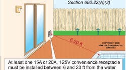
At least one 15A or 20A, 125V receptacle is required to be located between 6 ft and 20 ft from the inside walls of a permanently installed pool at a dwelling unit with a maximum height of not more than 6½ ft above the grade or floor [680.22(A)(3)] ( Fig. 1 on page 28).
In addition to the receptacle requirements just mentioned, 680.22 includes specific requirements for:
-
Luminaires (not underwater).
-
Ceiling fans.
-
Switching devices.
-
Other outlets (e.g., remote-control, signaling, fire alarm, and communications circuits).
Underwater luminaires
You must install an underwater luminaire so the top of the lens is at least 18 in. below the normal water level of the pool, unless it's listed and identified for use at lesser depths [680.23(A)(5)]. Transformers used to supply underwater luminaires must be listed as a swimming pool and spa transformer — and be of the isolating-winding type with a grounded metal barrier between the primary and secondary windings [680.23(A)(2)]. Branch circuits that supply underwater luminaires greater than 15V must be GFCI protected [680.23(A)(3)].
In 680.2, the NEC defines three general categories of underwater luminaires. Specifics, such as the wiring methods allowed to the forming shell and bonding requirements, are included for each type as follows:
- Wet-niche [680.23(B)].
- Dry-niche [680.23(C)].
- No-niche [680.23(D)].
Branch circuit wiring
Branch circuit wiring to supply underwater luminaires may use rigid metal conduit, intermediate metal conduit, liquidtight flexible nonmetallic conduit, PVC conduit, or reinforced thermosetting resin conduit [680.23(F)(1)].
If installing raceway on buildings, you can use electrical metallic tubing. Within buildings, you can use electrical nonmetallic tubing, Type MC cable, electrical metallic tubing, or Type AC cable. These must contain an insulated equipment grounding conductor sized per 250.122 but no smaller than 12 AWG [680.23(F)(1)].
Where connecting to transformers for pool lights, you can use liquidtight flexible metal conduit or liquidtight flexible nonmetallic conduit in individual lengths not exceeding 6 ft [680.23(F)(1) Ex].
Conductors
The branch circuit conductors on the load side of a GFCI or transformer for underwater luminaires must not occupy raceways or enclosures containing other conductors, unless the GFCI protected conductors are within a panelboard or the other conductors are [680.23(F)(3)]:
-
GFCI protected,
-
Grounding conductors, or
-
Supply conductors to a feed-through type GFCI.
Enclosures for junction boxes, transformers, or GFCIs
The junction box that connects directly to the luminaire forming shell must provide electrical continuity between metal raceways and grounding terminals within the junction box [680.24(B)(1)]. In addition, it must be:
-
Equipped with threaded entries or a nonmetallic hub.
-
Constructed of copper, brass, suitable plastic, or corrosion-resistant material approved by the authority having jurisdiction.
-
Provided with at least one more grounding terminal than the number of raceway entries [680.24(D)].
-
Provided with a strain relief for the cord [680.24(E)].
For luminaires greater than 15V, the junction box must be at least [680.24(A)(2)]:
-
4 in. above the ground or pool deck or not less than 8 in. above the maximum water level ( Fig. 2 ).
-
4 ft from the inside wall of the pool, unless separated by a solid fence, wall, or other permanent barrier.
For luminaires less than 15V, you can use a flush deck box if [680.24(A)(2)]:
-
An approved potting compound prevents the entrance of moisture.
-
The flush deck box is at least 4 ft from the inside wall of the pool.
Feeders
In 680.25, the feeders on the supply side of panelboards supplying branch circuits for pool equipment covered in Part II of Art. 680 are covered. Feeders may be installed in rigid metal conduit, intermediate metal conduit, liquidtight flexible nonmetallic conduit, PVC conduit, or reinforced thermosetting resin conduit [680.25(A)].
If installing feeder raceways on or within buildings, electrical metallic tubing is allowed. Within buildings, you can also use electrical nonmetallic tubing. Aluminum conduit is not permitted in the pool area where subject to corrosion.
An insulated equipment grounding conductor must be included with the feeder conductors between the grounding terminals of the equipment panelboard and the applicable service equipment or source of a separately derived system. Size the equipment grounding conductor per 250.122, but not smaller than 12 AWG. If fed from a separately derived system, this conductor must be sized in accordance with Table 250.66, but not smaller than 8 AWG.
If the feeder runs to a separate structure, then an insulated equipment grounding conductor must be installed with the feeder conductors to the disconnecting means at the separate structure [250.32(B)].
Equipotential bonding
The requirements in 680.26 are easier to understand if you remember the purpose of equipotential bonding is to prevent differences in potential. Essentially, you connect all of the metallic parts around the pool, outdoor spa, or hot tub with a conductive pathway ( Fig. 3 ).
In 680.26(B), you'll find seven types of “parts” to bond:
-
Conductive pool shells
Unencapsulated rebar bonded by steel tie wires may be used to bond the conductive shell. If this is not present, a copper conductor grid must be constructed.
-
Perimeter surfaces
An equipotential bonding grid must extend 3 ft horizontally beyond the inside walls of a pool. That includes unpaved, paved, and poured concrete surfaces.
-
Metallic components
Bond all metallic parts of the pool to the equipotential grid.
-
Underwater metal forming shells
Bond metal forming shells and mounting brackets for luminaires to the equipotential grid.
-
Metal fittings
If a metal fitting is 4 in. or larger and penetrates into the pool, bond it to the equipotential grid. This includes ladders and handrails.
-
Electrical equipment
Bond metal parts of pool covers and metal parts of electrical equipment associated with the water circulating system, such as water heaters and pump motors, to the equipotential grid.
Exception: You don't have to bond metal parts of listed equipment incorporating an approved system of double insulation. If installing a double-insulated water pump motor, provide a solid 8 AWG copper conductor from the bonding grid. This will be available for any future replacement motor that might not be double-insulated.
Ground and bond pool water heaters per equipment instructions. If those instructions conflict with Art. 250, contact the manufacturer.
-
Metal wiring methods and equipment
Bond all metal-sheathed cables, metal-sheathed raceways, metal piping, and fixed metal parts to the equipotential grid.
Exceptions: 1) Where separated from the pool by a permanent barrier; 2) Where located more than 5 ft (horizontally) from the inside walls of the pool; and 3) Where located more than 12 ft (vertically) above the maximum water level.
In addition, a minimum conductive surface area of 9 sq in. must be installed in contact with the pool water [680.26(C)]. This water bond can consist of metal parts that are required to be bonded in 680.26(B).
Specialized equipment
In 680.27, you'll find requirements for underwater audio equipment, electrically operated pool covers, and deck area heating. For electrically operated covers, the associated motors, controllers, and wiring must be at least 5 ft from the inside wall of the pool unless separated by a permanent barrier. The motor and controller circuit also must be GFCI protected.
Putting it all together
If you take a quick look at Art. 680 Part II, you might wonder how you can keep from drowning in detail. The answer is to sort out the requirements that apply to the specific equipment you're installing, rather than trying to understand and apply all the details at once.
Copyright 2009 by Penton Business Media Inc. All rights reserved.


