NEC Rules on Alternative Energy Systems — Part 1
Solar and wind are two alternative energy technologies that are increasingly providing work for electrical contractors. Fuel cell systems also fall into this category; however, this technology is still fighting to gain wide-scale adoption. All three of these systems require expertise in several non-electrical areas, which the NEC doesn’t address. But the NEC does provide requirements that seek to reduce the electrical hazards that may arise from installing and operating such systems.
In Part 1 of this two-part series, we’ll focus on solar power installations. Part 2 will address the NEC requirements associated with fuel cell and small wind power systems.
The requirements for solar power installations are in Art. 690, which consists of nine Parts — the ninth of which applies only to systems greater than 600V. The requirements of Chapters 1 through 4 of the NEC also apply to solar power installations, except as specifically modified by Art. 690. With the 2012 Code revision, Art. 690 replaces the term “photovoltaic” with the industry’s commonly used acronym “PV.” It does that with the term “solar” as well.
Installation
Section 690.4 includes many changes that clarify and expand the requirements for PV systems. For example:
- Where conductors of more than one system occupy the same enclosure (or raceway with a removable cover), you must group the conductors unless grouping is obviously not necessary [690.4(B)(1)(d) and Ex].
- When routing PV-related conductors along structural members, you have to mark their location if it’s not obvious. This helps protect firefighters who ventilate a roof where PV conductors are present [690.49F)].
- When you install multiple inverters remote from each other, you must additionally install a permanent plaque or directory denoting all electrical power sources on or in the premises [690.4(H)]. Where all inverters and PV DC disconnecting means are grouped at the main service disconnecting means, the plaque or directory is optional [690.4(H) Ex].
- Now only qualified persons can install PV systems. Other (and arguably more dangerous) areas of the Code have never required this, as this concern is typically covered by state or local agencies and their applicable licensing regulations. Many people consider this change to be revolutionary. It may set an interesting precedent for future editions of the NEC [690.4(E)].
The 2011 NEC added an Informational Note to 690.7, referring the Code user to the temperature data in the ASHRAE Handbook — Fundamentals. This addition should result in a more uniform interpretation and enforcement of the requirements for maximum PV voltage calculations.
Circuit sizing and protection
The sizing provisions for conductors and overcurrent devices now align with other Code requirements for conductors and overcurrent devices. Although Code Chapters 1 through 4 (including the conductor and overcurrentdevice rules) already apply [90.3], some PV system installers may not understand that — or they might not be proficient with applying the rules from Chapters 1 through 4.
To make it easier for these people, the 690.8 conductor and overcurrent device rules have been “copied and pasted” into this section. Section 690.8 includes rules for determining maximum circuit currents. Those rules are:
- PV Source Circuit Current (Isc). Multiply the module nameplate short circuit current rating (Isc) by 125% [690.8(A)(1)].
- PV Output Circuit Current. Add up the parallel PV Source Circuit Currents [690.8(A)(2)].
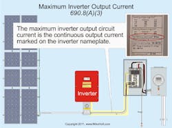
- Inverter Output Circuit Current. According to 690.8(A)(3), this is equal to the continuous output current marked on the inverter nameplate (Fig. 1).
- Stand-Alone Inverter Input Circuit Current. It’s the stand-alone continuous inverter rating when the inverter is producing power at the lowest rated voltage [690.8(A)(4)].
Sizing overcurrent protection devices (OCPDs)
Size OCPDs to carry not less than 125% of the current as calculated in 690.8(A) [690.8(B)(1)(a)], and:
- Apply the terminal temperature limits of 110.14(C) [690.8(B)(1)(b)].
- If operating above 40˚C, use the manufacturer’s temperature correction factors to adjust the ampacity rating of the OCPD [690.8(B)(1)(c)].
- Use settings or ratings permitted for OCPDs by 240.4(B), (C), and (D) [690.8(B)(1)(d)]
For OCPDs 800A or less, you can use the next higher standard rating of an OCPD listed in 240.6 (above the ampacity of the ungrounded conductors being protected) — but only if you satisfy all three conditions listed in 240.4(B).
You must size the circuit conductors to carry the larger of:
- 125% of the currents as calculated in 690.8(A) before the application of conductor adjustment and correction of 310.15 [690.8(B)(2)(a)].
- The maximum current calculated in 690.8(A) after the application of conductor adjustment and correction of 310.15 [690.8(B)(2)(b)].
You must size the conductor overcurrent protection to the conductor ampacity after the application of conductor adjustment and correction of 310.15 per 240.4(B), 240.4(C), and 240.4(D).
Overcurrent protection
A change to 690.9(E) clarifies that the single overcurrent device being discussed can protect both the module and the source conductors.
The exception to 690.9(A) now includes language about the maximum overcurrent device of the PV module. Where the short circuit current of the PV modules or PV source does not exceed the ampacity of the conductors or equipment, there is no hazard of overcurrent. Consequently, there is no need for overcurrent protection.
You must protect PV source circuits, PV output circuits, inverter output circuits, and equipment per the requirements of Art. 240. However, you do not have to provide overcurrent protection for PV direct-current circuits where the short-circuit currents (Isc) from all sources do not exceed the [690.9(A) Ex]:
- Ampacity of the PV circuit conductors, or
- Maximum overcurrent device size specified on the PV module nameplate (Fig. 2).
Stand-alone systems
Provisions for backfed circuit breakers have been added in 690.10(E). Although the requirements of Art. 408 already apply to PV installations [90.3], the 2011 Code revision borrows language from 408.36(D) and plunks it into 690. Because these rules were already in Art. 408, this change wasn’t a technical one.
Plug-in circuit breakers that are backfed from field-installed conductors must be secured in place by an additional fastener. This fastener must require something other than a pull to release the breaker from the panelboard. Circuit breakers that are marked line and load must not be backfed [690.10(E)].
The purpose of the breaker fastener is to prevent the circuit breaker from being accidentally removed from the panelboard while energized. That situation would expose someone to dangerous voltage.
Disconnecting
Part III of Art. 690 provides the requirements for the disconnecting means. Section 690.13 now includes an exception for switching devices that open the direct-current grounded conductor. The rule in 690.13 requires a disconnecting means that opens ungrounded direct-current circuit conductors. A switch, circuit breaker, or other device is not permitted to open the grounded direct-current conductor.
Exception 2 (which is new with the 2011 revision) allows you to install a disconnecting switch that opens the grounded direct-current conductor
(Fig. 3), but only if the switch is:
- Used only for PV array maintenance,
- Accessible only by qualified persons, and
- Rated for the maximum direct-current voltage and current, including ground fault conditions.
Why this change? It permits the standard practice of switching all circuit conductors of DC PV systems, including the grounded conductor. Now, we have specific requirements that help ensure a safe installation to qualified persons.
Fuses
A disconnecting means is now required for fuses on some PV output circuits. Why this new rule? Because replacing a fuse under load is obviously an unsafe work practice. Suppose the inverter has fuses on the input circuit fuses that combine the internal PV source and output circuit (a fairly common arrangement). And suppose they are connected directly to the inverter input terminals. There’s only one way to make this safe, which is to install an external disconnecting means.
Thus, 690.16 (A) requires you to provide a means to disconnect a fuse from all sources of supply if energized from both directions. The disconnect must be capable of being disconnected independently of fuses in other PV source circuits. One way to satisfy this requirement is to use disconnects with pull-out fuses (to disconnect a fuse from all sources of energy).
Similarly, 690.116 (B) requires you to install a disconnecting means for PV output circuits where fuses that must be serviced can’t be isolated from energized circuits. The disconnect must be:
- Within sight and accessible to the fuse or integral with the fuse holder.
- Externally operable without exposing the operator to contact with live parts.
- Plainly indicating whether in the open or closed position [690.17].
Where the disconnecting means is more than 6 ft from the fuse, then at the fuse location you must install a directory showing the location of the fuse disconnect. Mark any non-load-break rated disconnecting means: “Do not open under load.”
Wiring methods
The 2011 NEC extensively revised the rules for PV system wiring methods. For example, the 2011 revision:
- Provides a new Informational Note to 690.31, clarifying how to perform raceway fill calculations when using cables. This Note correlates with Note 5 in Chapter 9.
- Allows you to use Type MC cable as a wiring method for PV system source or output conductors run inside a building [690.31(E)].
- Adds requirements for separating conductors from the undersides of roofs. Like the identification requirement [690.4(F)], this helps prevent firefighters from cutting through energized conductors while ventilating the roof [690.31(E)(1)].
- Adds marking and labeling requirements, to reduce the likelihood of improper connection to conductors [690.31(E)(4)].
Equipment bonding
Unfortunately, Art. 690 retains the use of “grounding” where it means “bonding” (see Art. 100 definitions). Wherever you see “equipment grounding,” such as in 690.43 (or elsewhere in the NEC), the intent is equipment bonding. However, the 2011 NEC provided much better formatting of the equipment “grounding” provisions of Art. 690, Part V. When multiple requirements or provisions are in a single section, a “list” format is often easier to read and understand. Section 690.43 now reflects that fact. This revision also includes some technical changes. For example:
- Subsection (C) now requires that metal mounting racks be identified as equipment grounding conductors (EGCs) or have a bonding jumper(s) or devices installed between the separate metallic sections (Fig. 4). In addition, the metallic racks must be connected to the grounding system, which can be done via an equipment grounding conductor.
- Subsection (D) (added with the 2011 revision) requires that devices for securing PV modules be identified for equipment grounding if they’re used as an EGC.
Grounding electrode system
In contrast to “equipment grounding conductor,” the NEC really does mean “grounding” when it talks about the grounding electrode system. The key changes to requirements for PV grounding electrode systems [690.47] are:
- Section 690.47(B) now is clear that you can use a common grounding electrode conductor (GEC) to ground multiple inverters. This concept isn’t new to the NEC; similar provisions are in 250.30 for separately derived systems.
- Section 690.47(C) underwent extensive revision, with the intention of incorporating the concepts of the 2005 and 2008 editions into clear, easily understandable text.
- Section 690.47(D) wasn’t revised; it was deleted. It required ground and pole-mounted PV arrays to have a grounding electrode. The intention in the 2008 revision was for this to be optional, but the language used made it mandatory. Deleting Sec. 690.47(D) makes the rule optional again.
All of 690.47(C) is worth reading closely, but let’s look at its last paragraph. Subsection 690.47(C)(3) allows you to use a single conductor as the DC grounding electrode conductor (GEC) as well as for the AC equipment grounding conductor. This GEC must beunspliced (or irreversibly spliced). Run it from the marked direct-current grounding electrode connection point along with the alternating-current circuit conductors to the grounding bus bar in the associated alternating-current equipment (Fig. 5).
You must size this GEC to the larger of 250.122 or 250.166, and install it per 250.64(E).
To prevent inductive choking of grounding electrode conductors, ferrous raceways and enclosures containing grounding electrode conductors must have each end of the raceway or enclosure bonded to the GEC per 250.92(B) [250.64(E)]. Nonferrous raceways don’t need to meet this requirement. To save a lot of time and effort, install the grounding electrode conductor in PVC conduit suitable for the application [352.10(F)].
Solar is one of the three major alternative energy sources covered by the NEC. We’ll look at fuel cells and small-scale wind in our next issue. In the meantime, consider a couple of points about these types of systems.
Fuel cell systems still rely on fossil fuels (typically, a small-scale system uses natural gas). Even so, such systems usually reduce overall consumption of fossil fuels considerably.
The most common barrier to adopting wind systems is the irregularity of the wind. Developments in load management for large-scale systems are making this much less of an issue than it used to be. In fact, in April of this year, Xcel Energy (Colorado’s largest electric utility, serving about 55% of the state’s market) generated 57% of its electric power from wind. That kind of success is filtering down into the small-scale wind market, and helping increase demand.
Holt is the owner of Mike Holt Enterprises, Inc., Leesburg, Fla. He can be reached at www.mikeholt.com.
About the Author

Mike Holt
Mike Holt is the owner of Mike Holt Enterprises (www.MikeHolt.com), one of the largest electrical publishers in the United States. He earned a master's degree in the Business Administration Program (MBA) from the University of Miami. He earned his reputation as a National Electrical Code (NEC) expert by working his way up through the electrical trade. Formally a construction editor for two different trade publications, Mike started his career as an apprentice electrician and eventually became a master electrician, an electrical inspector, a contractor, and an educator. Mike has taught more than 1,000 classes on 30 different electrical-related subjects — ranging from alarm installations to exam preparation and voltage drop calculations. He continues to produce seminars, videos, books, and online training for the trade as well as contribute monthly Code content to EC&M magazine.