
Thank you for visiting one of our most popular classic articles. If you’d like to see updated information on this topic, please check out this recently published article, Motor Calculations — Part 1. |
Note: This article is based on the 2011 NEC.
Article 430 provides the requirements for electric motors while Art. 440 offers amended and additional requirements for hermetic motors, such as those used in air-conditioning and refrigeration equipment. Motor applications are complex, because they’re inductive loads with a high-current demand at startup. Because this inrush is typically six times the running current, overcurrent protection for motor applications must differ from other equipment.
You might be uncomfortable with some of the Art. 430 allowances for overcurrent protection. But once you understand how motor protection works, you’ll understand why these allowances are not only safe, but also necessary.
Table FLC versus motor nameplate current rating (FLA). The motor full-load current ratings listed in Tables 430.247, 430.248, and 430.250 are used to determine:
- Conductor ampacity [430.22].
- Branch circuit short circuit and ground fault overcurrent device size [430.52 and 430.62].
- Ampere rating of disconnecting switches [430.110].
The table selected for this purpose depends on the type of motor being used. The correct full-load current (FLC) is selected from:
- Table 430.247 direct current motors
- Table 430.248 single-phase motors
- Table 430.250 3-phase motors
However, for some specific types of motors, the actual nameplate full-load amperes (FLA) must be used instead of the FLC (see FLA vs. FLC).
Use the nameplate FLA when sizing conductors, branch circuit short circuit and ground fault protection, and disconnecting switches for:
- Motors built to operate under 1,200 rpm.
- Motors that have high torques (and thus higher FLCs).
- Multispeed motors (FLC varies with speed).
- A listed motor-operated appliance.
Also, use the nameplate FLA for sizing of separate motor overload protection [430.6(A)(2)].
Conductor size
If for a single motor, size conductors at least 125% of the motor FLC rating as listed in Table 430.247 [Direct-Current Motors], Table 430.248 [Single-Phase Motors], or Table 430.250 [Three-Phase Motors] (430.22). Let’s review a sample problem for clarity.
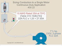
What size 75°C branch circuit conductor is required for a 7½-hp, 230V, 3-phase motor, as shown in Fig. 1?
Motor FLC = 22A [Table 430.250]
Conductor’s size = 22A × 1.25 = 27.50A
A check of Table 310.15(B)(16) reveals that a 10 AWG conductor is rated 30A at 75°C.
Note: The branch circuit short circuit and ground fault protection device using an inverse time breaker is sized at 60A, according to 430.52(C)(1) Ex 1:
Circuit protection = 22A × 2.50 = 55A, next size up 60A [240.6(A)]
Circuit conductors that supply several motors must not be smaller than the minimum ampacity found by adding [430.24]:
- 125% of the FLC of the highest rated motor.
- The FLCs of other motors
For this purpose, the highest rated motor is the one with the highest FLC [430.17]. Let’s review another example for clarity.
What size 75°C feeder conductor is required for two 7½-hp, 230V, 3-phase motors if the terminals are rated for 75°C?
Motor FLC = 22A [Table 430.250]
Motor feeder conductor = (22A × 1.25) + 22A = 49.50A
A check of Table 310.15(B)(16) reveals that an 8 AWG conductor is rated 50A at 75°C.
Note: The feeder overcurrent device (inverse time circuit breaker) must comply with 430.62 as follows:
Step 1: Determine the largest branch circuit overcurrent device rating [240.6(A) and 430.52(C)(1) Ex 1]: 22A × 2.50 = 55A, next size up is 60A
Step 2: Size the feeder overcurrent device in accordance with 240.6(A) and 430.62: 60A + 22A = 82A, next size down is 80A
Note: The “next-size-up protection” rule for branch circuits [430.52(C)(1) Ex 1] doesn’t apply to motor feeder short circuit and ground fault protection device sizing.
Taps
For motor circuit conductors tapped from a feeder [430.28], determine the ampacity per 430.22. The tap conductors must terminate in a branch circuit short circuit and ground fault protection device sized per 430.52.
Motor feeder tap conductors must have an ampacity that’s at least:
- One-tenth the rating of the feeder protection device, if not over 10 ft.
- One-third the ampacity of the feeder conductor, if over 10 ft but not over 25 ft.
- As large as the feeder conductor ampacity.
Overload protection
A fault, such as a short circuit or ground fault, isn’t an overload [Art. 100]. Overload is the operation of equipment in excess of its current rating — or where current is in excess of the conductor ampacity.
Sustained overload will dangerously overheat the equipment or even destroy it. So we want to protect motors, motor control equipment, and motor branch circuit conductors against excessive heating from overload. You must install an overload protection device for each ungrounded conductor [430.37].
Motor circuit overload protection requirements are in Art. 430, Part III. These are for overload and failure-to-start protection only. Overload protection isn’t required if it might introduce additional or increased hazards, as in the case of fire pumps (see 695.7).
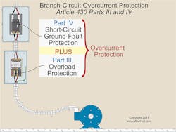
Because of the difference between starting and running current (see Starting, Running, and Locked), overcurrent protection for motors differs from that of other circuits. Generally, the motor overload device is separate from the short circuit and ground fault protection device (Art. 430 Part IV) [Fig. 2].
Overload devices come in many configurations. They can be conventional “heaters” or electronic. You can use a fuse sized per 430.32. If you use fuses for overload protection, provide one for each ungrounded conductor [430.36].
You can use a single overcurrent device to protect a motor against overload, short circuit, and ground fault [430.55]. However, you must size it to the overload requirements in 430.32.
Continuous duty
Motors rated more than 1 hp, used in a continuous-duty application without integral thermal protection, must have an overload device sized to open at no more than 115% of the motor nameplate FLC rating [430.32(A)(1)]. But size the overload device no more than 125% of the nameplate FLC if:
- The nameplate service factor (SF) is 1.15 or more.
- The nameplate temperature rise is 40°C or less.
Branch circuit short circuit and ground fault protection
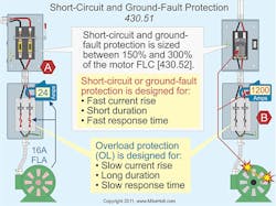
A branch circuit short circuit and ground fault protective device protects the motor, the motor control equipment, and the conductors against short circuits or ground faults. It does not protect against overload [430.51] (Fig. 3).
The motor branch circuit short circuit and ground fault protective device must be capable of carrying the motor’s starting current [430.52(B)]. Install a branch circuit short circuit and ground fault protective device on each motor circuit, and ensure that it is sized no greater than the percentages listed in Table 430.52. Let’s take a look at another example problem.
What size 75°C conductor and inverse time circuit breaker are required for a 2-hp, 230V, single-phase motor?
Step 1: Determine the branch circuit conductor [Table 310.15(B)(16), 430.22, and Table 430.248]: 12A × 1.25 = 15A
As per Table 310.15(B)(16), a 14 AWG conductor is rated 20A at 75°C.
Step 2: Determine the branch circuit protection [240.6(A), 430.52(C)(1), and Table 430.248]: 12A × 2.50 = 30A
Overcurrent protection for motors is different than protection for other types of electrical loads, and the values you come up with might not seem right based on your experience with other types of applications. Protecting a 14 AWG conductor with a 30A circuit breaker, for example, just looks wrong. But keep in mind that motor branch circuit conductors are protected against overloads by the overload device. That device is sized between 115% and 125% of the motor nameplate current rating [430.32].
The small conductor rule contained in 240.4(D), which limits 15A protection for 14 AWG, doesn’t apply to motor circuit protection. See 240.4(D) and 240.4(G).
Feeder protection
You need to protect motor feeder conductors against short circuits and ground faults. But how do you size the protective device to handle this job? First, determine which motor on the feeder has the largest rated branch circuit short circuit and ground fault protective device. Next, add up the FLCs of the other motors in the group. Finally, add that sum to the device rating from the first step [430.62(A)].
The “next-size-up protection” rule for branch circuits [430.52(C)(1) Ex 1] doesn’t apply to a motor feeder protection device rating. Thus, you may need to round down to the protection device that “does not exceed” that calculated value. An example problem helps illustrate this.
What size feeder protection (inverse time breakers with 75°C terminals) and 75°C conductors do you need for the following two motors (Fig. 4)?
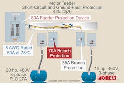
Motor 1 — 20 hp, 460V, 3-phase = 27A FLC [Table 430.250]
Motor 2 — 10 hp, 460V, 3-phase = 14A FLC
Here’s the solution:
Step 1: Determine the feeder conductor size [430.24]: (27A × 1.25) + 14A = 48A
8 AWG rated 50A at 75°C [110.14(C)(1) and Table 310.15(B)(16)]
Step 2: Feeder protection [430.62(A)] isn’t greater than the largest branch circuit ground fault and short circuit protective device plus the other motor FLC.
Step 3: Determine the largest branch circuit ground fault and short circuit protective device [430.52(C)(1) Ex]: 20 hp motor = 27A × 2.50 = 68, next size up = 70A
10 hp motor = 14A × 2.50 = 35A
Step 4: Determine the feeder protection: not more than 70A + 14A, = 84A.
Next size down = 80A [240.6(A)]
Therefore, for this specific arrangement, you would use 8 AWG conductor and an 80A breaker.
Article 430 road map. Compared to other NEC Articles, Art. 430 is long and complex. But now that you have a good overview of its requirements, you can combine this knowledge with the “map” shown in Figure 430.1 to boost your calculation efficiency and accuracy.
SIDEBAR 1: Starting, Running, and Locked
A motor draws significantly more current when starting than when running. It draws even more in a locked-rotor condition.
- Starting current. When voltage is first applied to the field winding of an induction motor, only the conductor resistance opposes the flow of current through the winding. Because conductor resistance is very low, the motor has a large inrush current.
- Running current. Once the rotor reaches rated speed, the starting current reduces to running current due to the counter-electromotive force (CEMF).
- Locked-rotor current (LRC). If the rotating part of the motor winding (armature) can’t rotate (for instance, due to a jam), then the winding produces no CEMF. Consequently, conductor impedance decreases until it’s effectively a short circuit. The motor operates at LRC, often six times the full-load ampere rating, depending on the motor code letter rating [430.7(B)]. The resulting overheating of the motor winding will destroy the winding if the current isn’t quickly reduced or removed.
SIDEBAR 2: FLA Vs. FLC
The nameplate full-load ampere (FLA) rating is the current the motor draws while producing its rated horsepower load at its rated voltage, based on its rated efficiency and power factor. The current the motor actually draws depends on the actual voltage at the motor terminals and the load the motor is trying to drive. The current increases if the load increases or if the voltage decreases.
Caution: To prevent damage to motor windings from excessive heat (caused by excessive current), never load a motor above its horsepower rating, and be sure the voltage source matches the motor’s voltage rating.
The full-load current (FLC) tables are found at the end of Art. 430. In general terms, the permanent wiring installed for motor circuits is sized based on these tables, which are intended to be large enough for any motor design of a particular horsepower rating.
About the Author

Mike Holt
Mike Holt is the owner of Mike Holt Enterprises (www.MikeHolt.com), one of the largest electrical publishers in the United States. He earned a master's degree in the Business Administration Program (MBA) from the University of Miami. He earned his reputation as a National Electrical Code (NEC) expert by working his way up through the electrical trade. Formally a construction editor for two different trade publications, Mike started his career as an apprentice electrician and eventually became a master electrician, an electrical inspector, a contractor, and an educator. Mike has taught more than 1,000 classes on 30 different electrical-related subjects — ranging from alarm installations to exam preparation and voltage drop calculations. He continues to produce seminars, videos, books, and online training for the trade as well as contribute monthly Code content to EC&M magazine.