Grounding and Bonding of Separately Derived Systems
Separately derived systems (SDSs) include most transformers as well as any generator or UPS supplying a transfer switch that opens the neutral conductor. What makes a system “separately derived?” It's sourced from something other than a service — where there is no direct electrical connection between the two systems [Art. 100].
This lack of a direct connection raises some interesting questions relating to safety and power quality. That SDS will necessarily be at a different potential (voltage) from other systems. So, for example, what happens when you transfer the load from the service, where the metal parts of the electrical equipment are connected to the service neutral, but not the generator neutral? The NEC answers such questions in 250.30 by providing the requirements for SDSs.
System bonding jumper
The system bonding jumper is a conductor, screw, or strap that bonds the metal parts of an SDS to the system neutral point [250.2]. The system bonding jumper provides a low-impedance fault current path to the power supply to facilitate the clearing of a ground fault by opening the circuit overcurrent device.
During a ground fault, metal parts of electrical equipment, metal piping, and structural steel will become energized. This situation provides the potential for electric shock and fire. The system bonding jumper resolves this situation by creating a path from the metal parts back to the source and allows overcurrent devices to operate, thereby removing the dangerous condition.
Dangerous objectionable neutral current will flow on conductive metal parts of electrical equipment, metal piping, and structural steel if you install more than one system bonding jumper. Because of this, you can't have a neutral-to-case connection on the load side of the system bonding jumper, except as permitted in 250.142(B).
You also get objectionable neutral current if the system bonding jumper is located somewhere other than where the grounding electrode conductor (GEC) terminates to the neutral conductor. You can terminate the GEC to the neutral conductor either at the SDS or at the system disconnecting means. But pick one — you can't have it in both locations [250.30(A)(3)].
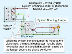
If you install the bonding jumper at the disconnecting means (Fig. 1):
-
Route the neutral conductor with the secondary conductors.
-
Size the neutral conductor no smaller than specified in Table 250.66, based on the area of the secondary conductors.
-
If you install the secondary conductors in parallel, size the neutral secondary conductor in each raceway (or cable) no smaller than specified in Table 250.66, based on the area of the largest ungrounded conductor in the raceway (or cable). Remember that in no case can you size the neutral conductor smaller than 1/0 AWG [310.4].
-
An equipment bonding jumper must connect the metal parts of the SDS to the neutral conductor at the disconnecting means per 250.30(A)(2).
Equipment bonding jumpers
You must run an equipment bonding jumper to the secondary system disconnecting means, regardless of where the system bonding jumper is installed. Where the equipment bonding jumper is of the wire type, size it per Table 250.66, based on the area of the secondary conductor in the raceway or cable [250.102(C)].
Grounding electrode conductor (GEC)
You must install a GEC to connect the neutral terminal of an SDS to a grounding electrode of a type identified in 250.30(A)(7) [250.30(A)(3)]. You don't have to do this, however, if your SDS is for a Class 1, Class 2, or Class 3 circuit, and is rated 1 kVA or less [250.30(A)(3) Ex No. 1]. Size the GEC per 250.66, based on the area of the secondary conductor.
To prevent objectionable neutral current [250.6] from flowing onto metal parts, the GEC must originate at the same point on the SDS where the system bonding jumper is connected [250.30(A)(1)].
What if you have multiple SDSs? In such a case, you can connect the neutral terminal of each derived system to a common GEC. The GEC must not be smaller than 3/0 AWG copper. Size GEC taps per Table 250.66, based on the area of the secondary conductor.
For multiple SDSs, you also have to make GEC tap connections at an accessible location by:
-
Listed connectors.
-
Listed connections to aluminum or copper bus bars not less than ¼ inch by 2 inches. If using aluminum bus bars, they must comply with 250.64(A).
-
Exothermic welding.
Connect grounding electrode taps to the common GEC so the common GEC isn't spliced.
The GEC must be:
-
Of copper where within 18 inches of earth [250.64(A)].
-
Securely fastened to the surface on which it's carried [250.64(B)].
-
Adequately protected if exposed to physical damage [250.64(B)].
Metal enclosures enclosing a GEC must be made electrically continuous from the point of attachment to cabinets or equipment to the grounding electrode [250.64(E)].
System grounding reduces overvoltage caused by induction from indirect lightning, or restriking/intermittent ground faults. Induced voltage imposed from lightning can be reduced by short grounding conductors and eliminating unnecessary bends and loops [250.4(A)(1) FPN].
System grounding also helps reduce voltage stress on electrical insulation, thereby ensuring longer insulation life for motors, transformers and other system components.
Grounding electrode
Install the grounding electrode as close as possible to where the system bonding jumper is located. Preferably, it will be in the same area as that jumper. What can you use for a grounding electrode? Per 250.52(A), you can use a metal water pipe electrode or structural metal electrode [250.30(A)(7)] (Fig. 2). But what if you don't have one of those electrodes present? The NEC makes allowances for just such a situation. You have to use one of the following:
-
Concrete-encased electrode. It has to be encased by at least 2 inches of concrete. The question is, do you stand that electrode up vertically or lay it down horizontally? Either way is acceptable, if the electrode is within that portion of concrete foundation or footing that is in direct contact with the earth. If it's horizontal, it needs to be near the bottom of the encasement. The electrode itself has to be at least 20 feet of electrically conductive steel reinforcing bars or rods of not less than ½ inch diameter, or it can be 20 feet of 4 AWG conductor [250.52(A)(3)].
-
Ground ring. This must encircle the structure and be buried at least 30 inches below grade. The ring must consist of at least 20 feet of bare copper conductor not smaller than 2 AWG [250.52(A)(4) and 250.53(F)].
-
Ground rod. It needs at least 8 feet of contact with the soil. It must meet the requirements of 250.56 [250.52(A)(5) and 250.53(G)]. To get the 25 ohms resistance, you may need to drive an additional rod. You don't have to keep driving rods until you get 25 ohms, however. The rule is you must drive a second one if the first one is higher than 25 ohms. The NEC requires you to place the second rod at least 6 feet from the first one, but it's even better if the rods are farther apart.
-
Other listed electrodes [250.52(A)(6)].
Steel and pipes
To ensure the quick removal of dangerous voltage from a ground fault in the area served by the SDS, connect the structural steel and metal piping of that area to the neutral conductor at the SDS per 250.104(D). What happens if you don't make this connection? You end up with a difference of potential (voltage) between your SDS and the structural steel and metal piping. During a fault condition, this could cause property damage from a fire and even prove fatal from electric shock. The fact that electricity seeks to get back to its source is a fundamental concept of electrical theory — a concept that will help you with your SDS applications.
Differences of potential (voltage) create hazards for people and equipment. Therefore, you don't want these to exist in your SDS. Nor do you want differences of potential (voltage) between systems. You have to eliminate these dangerous differences of potential (voltage) while keeping systems separate. How you achieve that is a matter of how you install and connect your system bonding jumper, equipment bonding jumpers, GEC, and other bonding and grounding components.
If you address each of these components per the requirements of 250.30, the electricity in your SDS will properly return to its source. More importantly, you will have averted the hazards arising from differences of potential (voltage).
About the Author

Mike Holt
Mike Holt is the owner of Mike Holt Enterprises (www.MikeHolt.com), one of the largest electrical publishers in the United States. He earned a master's degree in the Business Administration Program (MBA) from the University of Miami. He earned his reputation as a National Electrical Code (NEC) expert by working his way up through the electrical trade. Formally a construction editor for two different trade publications, Mike started his career as an apprentice electrician and eventually became a master electrician, an electrical inspector, a contractor, and an educator. Mike has taught more than 1,000 classes on 30 different electrical-related subjects — ranging from alarm installations to exam preparation and voltage drop calculations. He continues to produce seminars, videos, books, and online training for the trade as well as contribute monthly Code content to EC&M magazine.