Grounding and Bonding — Part 1 of 3
Most power quality and safety issues in electrical installations arise from misapplication of the grounding and bonding requirements of Art. 250. One common problem is installers ground where they should bond.
While the NEC provides clear descriptions of grounding and bonding in Art. 100, the words are often misused in the various articles. Typically, the error involves saying “grounding” instead of “bonding.” This error is even in nomenclature such as “equipment grounding conductor.” You should not be grounding your load side equipment. You should be bonding it.
Bonding is a means of providing electrical continuity between metallic objects. Simple definition, right? What’s not always simple is correctly applying the NEC requirements, some of which changed with the 2011 revision. That will be the focus of this article. Many of these changes were for the sake of clarity.
Service equipment
Bond all metal raceways and enclosures that contain (or support) service conductors [250.92]. Interestingly, the NEC requires raceways and enclosures that contain feeder or branch conductors to connect to the circuit “equipment grounding conductor” [250.86], which is actually a bonding conductor [Art. 100].
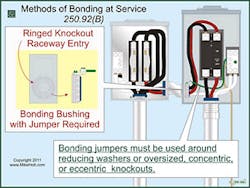
If a panel knockout is oversized, concentric, or eccentric, or uses reducing washers, bond around that opening. Use a bonding jumper, not a standard locknut (Fig. 1).
Fig. 1. If a panel knockout is oversized, concentric, or eccentric - or uses reducing washers - use a bonding jumper, not a standard locknut.
The NEC gives you the choice of four methods for ensuring electrical continuity at service equipment, service raceways, and service conductor enclosures [250.92(B):
- Bonding jumpers. Bond metal parts to the service neutral conductor. This requires a main bonding jumper [250.24(B) and 250.28]. Because the service neutral conductor provides the effective ground-fault current path to the power supply [250.24(C)], you don’t have to install an equipment grounding conductor within PVC conduit containing service-entrance conductors [250.142(A)(1) and 352.60 Ex 2] (Fig. 2).
- Threaded fittings. Terminate metal raceways to metal enclosures by threaded hubs on enclosures (if made wrenchtight).
- Threadless fittings. Terminate metal raceways to metal enclosures by threadless fittings (if made tight).
- Other listed devices. These include bonding-type locknuts, bushings, wedges, or bushings with bonding jumpers.
Fig. 2. An SSBJ isn't required within nonmetallic conduit because the service neutral conductor serves as the effective ground-fault current path.
This last method needs more discussion. To bond one end of the service raceway to the service neutral conductor, you must use a listed bonding wedge or bushing with a bonding jumper. Size it per Table 250.66, based on the area of the largest ungrounded service conductors within the raceway [250.102(C)].
When a metal raceway containing service conductors terminates to an enclosure without a ringed knockout, you can use a bonding-type locknut. Bonding one end of a service raceway to the service neutral provides the low-impedance fault current path to the source (Fig. 3).
Fig. 3. Bonding one end of a service raceway to the service neutral provides the low-impedence fault current path to the source.
Other systems
You can’t have “separate grounds” between communications systems and your service. You must provide an external intersystem bonding terminal (for connecting communications systems bonding conductors at service equipment) [250.94]. For structures supplied by a feeder, do this at the metering equipment enclosure and disconnecting means (Fig. 4).
Fig. 4. For structures supplied by a feeder, you must provide an external intersystem bonding terminal at the metering equipment enclosure and disconnecting means.
The resulting termination must:
- Be accessible for connection and inspection.
- Consist of a set of terminals with the capacity for connecting at least three intersystem bonding conductors.
- Not interfere with opening the enclosure for a service, building/structure disconnecting means, or metering equipment.
- Be securely mounted and electrically connected to service equipment, the meter enclosure, or exposed nonflexible metallic service raceway — or it must be mounted at one of these enclosures and connected to the enclosure or grounding electrode conductor. Use at least a 6 AWG copper conductor.
- Be securely mounted to the structure disconnecting means — or it must be mounted at the disconnecting means and connected to the enclosure or grounding electrode conductor. Use at least a 6 AWG copper conductor.
- Use terminals listed as grounding and bonding equipment.
Bonding conductors and jumpers
The 2011 revision helps distinguish between the rules for bonding jumpers upstream from an overcurrent device versus bonding jumpers downstream from an overcurrent device.
The NEC now clarifies that bonding jumpers on the load side of an overcurrent device must comply with all of Sec. 250.122, not just Table 250.122. It also:
- Clarifies the rules for bonding jumpers installed in a raceway versus those installed outside a raceway.
- Adds provisions for protecting aluminum bonding jumpers against corrosion.
- Addresses physical protection for all bonding jumpers.
Equipment bonding jumpers must:
- Be copper.
- Terminate by listed pressure connectors, terminal bars, exothermic welding, or other listed means [250.8(A)].
Supply-side bonding jumpers:
- Size these per Table 250.66, based on the largest ungrounded conductor within the raceway.
- If the ungrounded supply conductors are larger than 1,100kcmil copper or 1,750kcmil aluminum, size the bonding jumper at least 12.5% of the area of the largest set of ungrounded supply conductors.
- If the ungrounded supply conductors and the supply-side bonding jumper are of different materials, size the supply-side bonding jumper on the assumed use of the same material.
Size bonding jumpers on the load side of feeder and branch circuit overcurrent devices per 250.122, based on the rating of the circuit overcurrent device. The equipment bonding jumper doesn’t have to be larger than the largest ungrounded circuit conductors [250.122(A)].
If you use a single equipment bonding jumper to bond two or more raceways, size it per 250.122, based on the rating of the largest circuit overcurrent device.
You can install equipment bonding jumpers, bonding jumpers, or bonding conductors inside or outside of a raceway.
- If inside a raceway, these conductors must be identified per 250.119. If circuit conductors are spliced or terminated on equipment within a metal box, then the equipment grounding conductor associated with those circuits must be connected to the box per 250.148.
- If outside of a raceway, these conductors can’t be longer than 6 ft and must be routed with the raceway.
Piping systems and exposed structural metal
Metal-piping systems, such as sprinkler, gas, or air, that are likely to become energized must be bonded to the electrical system. This bonding prevents a difference of potential that can produce flashover and ignition.
The equipment grounding conductor (for the circuit that’s likely to energize the piping) can serve as the bonding means [250.104]. Via an Informational Note, the NEC now alerts the reader that the National Fuel Gas Code, NFPA 54, Sec. 7.13 contains further information about bonding gas piping.
If it’s likely to become energized, exposed structural metal that forms a metal building frame must be bonded to the one of the following:
- Service equipment enclosure.
- Service neutral conductor.
- Structure disconnecting means (structures supplied by a feeder or branch circuit).
- Grounding electrode conductor (if sufficiently sized).
- Grounding electrode system.
Size the bonding jumper per Table 250.66, based on the area of the ungrounded supply conductors. The bonding jumper must be copper if within 18 in. of the earth [250.64(A)], securely fastened to the surface on which it’s carried [250.64(B)] and adequately protected if exposed to physical damage [250.64(B)]. All points of attachment must be accessible, except as permitted in 250.68(A).
Separately derived systems
You must bond a separately derived system (SDS) to either the:
- Nearest available point of the metal water piping system in the area served by the SDS, or
- Structural metal building frame — but only if it serves as the grounding electrode [250.52(A)(1)] for the SDS.
You must bond the SDS to exposed structural metal (interconnected to form the building frame), unless the structural frame serves as the grounding electrode [250.52(A)(2)] for the SDS.
In all three of the above cases:
- Bond to the neutral point of the SDS at the grounding electrode conductor connection point [250.104(D)(1)].
- Size the bonding jumper per Table 250.66, based on the area of the largest ungrounded conductor of the derived system.
Previous NEC revisions required you to bond structural metal (if likely to become energized) to the service equipment enclosure. But what about a structure supplied by a feeder or branch circuit?
The 2011 revision makes it clear that you must bond the structural metal (if likely to become energized) to the disconnecting means of the structure, regardless of the type of circuit feeding the premises.
No pure-play
Figure 250.1 lays out Art. 250 into three informational blocks (plus a fourth that’s off to the side). We’ve now addressed bonding, which is off in a block by itself. But contrary to what 250.1 may indicate, the other blocks are not grounding pure-plays. In our next issue, we’ll see where grounding and bonding collide.