If you look at Fig. 230.1 in the NEC, you'll see that Art. 230 divides neatly into three general “blocks” of coverage. The first includes general requirements, overhead service drop conductors, and underground lateral conductors. These are covered by Art. 230 Parts I, II, and III, respectively.
The second and third blocks of Art. 230 provide requirements for service-entrance conductors and service equipment. We will address those in Part 2 of this article.
Number of services
Service drop conductors and underground lateral conductors are the conductors coming from the service point to the service entrance conductors or, sometimes, directly to the service equipment itself [see Art. 100 definitions starting with service and ending with service point].
Utility-owned conductors before the service point are outside of the scope of the NEC [90.2(B)(5)]. Therefore, they have no definitions or requirements.
A building or structure can be served by only one service drop or service lateral [230.2]. The exceptions are:
Special conditions
-
Fire pumps
-
Emergency systems
-
Legally required standby systems
-
Optional standby systems
-
Parallel power production systems
-
Systems designed for connection to multiple sources of supply for the purpose of enhanced reliability
-
Keep them separate
For special occupancies, and with written consent from the Authority Having Jurisdiction (AHJ) [Art. 100 Special Permission]
-
Multiple-occupancy buildings where there's no available space for supply equipment accessible to all occupants
Clearances
Capacity requirements
-
A building or other structure so large that two or more supplies are necessary
-
Where the capacity requirements exceed 2,000A, or where the load requirements of a single-phase installation exceed the utility's capacity
-
Service-drop conductor sizing
By written consent of the AHJ [Art. 100 Special Permission]
You can also have additional services for different voltages, frequencies, or phases — or for different uses, such as for different electricity rate schedules.
Where a structure is supplied by more than one service — or a combination of feeders and services — you must install a permanent plaque or directory at each service or building disconnect location to denote all other services and feeders supplying that structure (and the area served by each).
If you want a separate service for emergency or legally required systems [700.12(D) and 701.11(D)], you must get AHJ approval for it.
If you are using a separate service for a fire pump, emergency system, or standby power system, the disconnect must be located remotely away from the normal power disconnect [230.72(B)]. The reason for this requirement is to minimize the possibility of accidental interruption.
Service conductors must not pass through the interior of another structure [230.3]. Nor can you install them in the same raceway or cable with feeder or branch-circuit conductors [230.7].
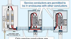
This rule doesn't prohibit the mixing of service, feeder, and branch-circuit conductors in the same service equipment enclosure (Fig. 1).
Overhead service conductors installed in a cable, or as individual open conductors, must be at least 3 ft from doors, porches, balconies, ladders, stairs, fire escapes, or similar locations [230.9(A)]. They must also be at least 3 ft from windows that open. If they run above a window, you don't have to maintain the 3 ft distance to that window (Fig. 2).
Maintain a vertical clearance of at least 10 ft above platforms, projections, or surfaces from which people might reach an overhead conductor [230.9(B) and 230.24(B)]. This vertical clearance must be maintained for 3 ft, measured horizontally from the platform, projections, or surfaces from which people might reach them, except:
-
If the slope of the roof exceeds 4 in. of vertical rise for every 12 in. of horizontal run, 120/208V or 120/240V conductor clearances can be reduced to 3 ft over the roof [240.24(B) Ex 2].
-
If no more than 6 ft of conductors pass over no more than 4 ft of roof, 120/208V or 120/240V conductor clearances over the roof overhang can be reduced to 18 in. [240.24(B) Ex 3] (Fig. 3).
Don't install service conductors under an opening through which materials might pass, nor where they will obstruct entrance to building openings [230.9(C)]. Finally, don't use vegetation as support [230.10].
Service-drop conductors must have adequate mechanical strength, and they must have sufficient ampacity to carry the load as calculated in Art. 220 [230.23].
Ungrounded service-drop conductors can't be smaller than 8 AWG copper or 6 AWG aluminum, except in limited-load installations, where they can be as small as 12 AWG [230.23(B)].
Continue on Page 2
Size the neutral service-drop conductor to carry the maximum unbalanced load, per 220.61, but don't size it smaller than required by 250.24(C) and Table 250.66. It can't be smaller than that, because it must have sufficiently low impedance and current-carrying capacity to safely carry fault current and thus facilitate operation of an overcurrent device.
See if you can correctly answer this question: What size neutral conductor in a service drop do you need for a structure with a 400A service supplied with 500kcmil conductors if the maximum line-to-neutral load is no more than 100A?
According to Table 310.16, 3 AWG rated 100A at 75°C [110.14(C)] is sufficient to carry 100A of neutral current. However, the service neutral conductor can't be sized smaller than 1/0 AWG (per Table 250.66, based on the area of the ungrounded service conductors) [250.24(C)]. Therefore, the correct answer is 1/0 AWG.
Service-drop conductor vertical clearances
Service-drop conductor spans must maintain a minimum of 8 ft above a roof surface, for a minimum distance of 3 ft in all directions from the edge of the roof [230.24(A)]. There are exceptions, however. For example, if the slope of the roof exceeds 4 in. of vertical rise for every 12 in. of horizontal run, you can reduce the clearances of 120/208V or 120/240V conductors to 3 ft over the roof.
Overhead conductor spans must maintain the following vertical clearances:
-
10 ft above finished grade, sidewalks, or platforms or projections from which they might be accessible to pedestrians for 120/208V or 120/240V circuits.
-
12 ft above residential property and driveways, and those commercial areas not subject to truck traffic for 120/208V, 120/240V, or 277/480V circuits.
-
18 ft over public streets, alleys, roads, parking areas subject to truck traffic, driveways on other than residential property, and other areas traversed by vehicles, such as those used for cultivation, grazing, forestry, and orchards.
If overhead service conductors are not under the exclusive control of the electric utility [90.2(B)(5)] but are located above pools, outdoor spas, outdoor hot tubs, diving structures, observation stands, towers, or platforms, then install them per the clearance requirements of 680.8.
Attachment
The point of attachment for service-drop conductors must be at least 10 ft above the finished grade. Choose a location that allows you to maintain the minimum service conductor clearance required by 230.9 and 230.24 [230.26]. This means you don't just attach it at 10 ft and 1 in. and call it good. You might need to raise the point of attachment so you still comply with 230.9 and 230.24.
When attaching multiconductor service cables, use only fittings identified for use with service conductors [230.27]. Attach open service conductors to fittings identified for use with service conductors or to noncombustible, nonabsorbent insulators securely attached to the building or other structure.
Support
The service mast used as overhead conductor support must have adequate mechanical strength (or braces or guy wires to support it) to withstand the strain caused by the service-drop conductors [230.28]. Some local codes require a minimum 2-in. rigid metal conduit for the service mast. In addition, many electric utilities contain specific requirements for the installation of the service mast.
The only conductors you can attach to a service mast are the electric utility service-drop conductors. Don't attach cabling from other systems to it. NEC 810.12 and 820.44(C) also specify that aerial cables for radio, TV, or CATV must not be attached to the service mast, and 810.12 prohibits antennas from being attached to the service mast. In addition, 800.133(B) and 830.133(B) prohibit communications and broadband cables from being attached to raceways, including a service mast (Fig. 4).
Underground service-lateral conductors
Underground service-lateral conductors under the exclusive control of an electric utility must comply with the National Electrical Safety Code (NESC), not the NEC [90.2(B)(5)]. Underground conductors that are not under the exclusive control of the electric utility must be installed in accordance with the NEC.
Service-lateral conductors must have adequate mechanical strength, and they must have sufficient ampacity to carry the load as calculated in Art. 220 [230.31(A)]. Service-lateral conductors must not be smaller than 8 AWG copper or 6 AWG aluminum [230.31(B)]. Exception: Service-lateral conductors can be as small as 12 AWG for limited-load installations.
Size the neutral service-lateral conductor to carry the maximum unbalanced load per 220.61. Don't size the service neutral conductor smaller than required by 250.24(C) and Table 250.66 [230.31(C)]. If you install service lateral conductors underground, make sure they have the minimum cover required by Table 300.5.
Now that we've reviewed the requirements for sizing and installing conductors that are coming from the service point, you've probably noticed Art. 230 presents these requirements in a logical sequence. You should be able to set your one-line diagram down right next to it and proceed straight through the requirements. In Part 2 of this article, you'll be able to make a similar observation.


