Don't Let Voltage Drop Get Your System Down
Thank you for visiting one of our most popular classic articles. If you’d like to see updated information on this topic, please check out this recently published article, Low-Voltage Motors, Voltage Drop, and the NEC. |
Contrary to common belief, the NEC generally doesn't require you to size conductors to accommodate voltage drop. It merely suggests in the Fine Print Notes to 210.19(A), 215.2(A)(4), 230.31(C), and 310.15(A)(1) that you adjust for voltage drop when sizing conductors. It's important for you to remember that Fine Print Notes are recommendations, not requirements [90.5(C)].
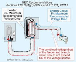
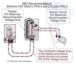
The NEC recommends that the maximum combined voltage drop for both the feeder and branch circuit shouldn't exceed 5%, and the maximum on the feeder or branch circuit shouldn't exceed 3% (Fig. 1). This recommendation is a performance issue, not a safety issue.
If the NEC doesn't require you to size for voltage drop, why even think about it? Consider these reasons:
- System efficiency — If a circuit supports much of a load, a larger conductor will pay for itself many times over in energy savings alone.
- System performance — Lighting loads perform best when voltage drop is minimal. You get the light of a higher-wattage system simply by running larger wires.
- Troubleshooting — If you follow the NEC voltage drop recommendations, you don't have to guess whether your field measurements indicate a problem or if the voltage is low due to not accommodating voltage drop in the design.
- Load protection — Undervoltage for inductive loads can cause overheating, inefficiency, and a shorter life span of the equipment. When conductor resistance causes the voltage to drop below an acceptable point, increase the conductor size.
What exactly is voltage drop?
The voltage drop of a circuit is in direct proportion to the resistance of the conductor and the magnitude of the current. If you increase the length of a conductor, you increase its resistance — and thus increase its voltage drop. If you increase the current, you increase the conductor voltage drop. Thus, long runs often produce voltage drops that exceed NEC recommendations.
To test your knowledge, take the following pop quiz. What is the minimum NEC-recommended operating voltage for a 115V load connected to a 120V source (Fig. 2)?
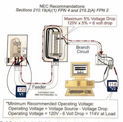
The maximum conductor voltage drop recommended for both the feeder and branch circuit is 5% of the voltage source (120V). The total conductor voltage drop (feeder and branch circuit) shouldn't exceed 120V×0.05=6V. Calculate the operating voltage at the load by subtracting the conductor voltage drop from the voltage source: 120V - 6V = 114V. Therefore, the correct answer is (c), 114V.
Doing the calculations
You can determine conductor voltage drop by using the Ohm's Law method or by the formula method, but you can only use the Ohm's Law method (I × R) for single-phase systems. Regardless of which method you use, observe the following:
- For conductors 1/0 AWG and smaller, the difference in resistance between DC and AC circuits is so little that it can be ignored. In addition, you can ignore the small difference in resistance between stranded and solid wires.
- VD = Voltage drop
- I = The load in amperes at 100%, not 125%, for motors or continuous loads
- R = Conductor resistance, Chapter 9, Table 8 for DC or Chapter 9, Table 9 for AC
Let's do a sample calculation using the Ohm's Law method. What is the voltage drop of two 12 AWG THHN conductors that supply a 16A, 120V load located 100 feet from the power supply?
(a) 3.2V
(b) 6.4V
(c) 9.6V
(d) 12.8V
The math is straightforward:
I = 16A
R = 2 ohms per 1,000 feet, according to Chapter 9, Table 9: (2 ohms ÷ 1,000 ft) × 200 ft = 0.4 ohms
VD = I × R
VD = 16A × 0.4 ohms = 6.4V
Therefore, the correct answer is (b), 6.4V.
Formula method
This method is slightly more involved than the Ohm's Law method, but the big advantage is you can use it for single-phase or 3-phase systems. Here are some additional items to observe:
- Single-phase VD = (2 × K × I × D) ÷ CM.
- 3-phase VD = (1.732 × K × I × D) ÷ CM.
- K = Direct-current constant. K represents the DC resistance for a 1,000-circular mils conductor that is 1,000 feet long, at an operating temperature of 75°C. K is 12.9 ohms for copper and 21.2 ohms for aluminum.
- Q = Alternating-current adjustment factor. For AC circuits with conductors 2/0 AWG and larger, you must adjust the DC resistance constant K for the effects of self-induction (eddy currents). Calculate the “Q” Adjustment Factor by dividing the AC ohms-to-neutral impedance listed in Chapter 9, Table 9 by the DC resistance listed in Chapter 9, Table 8.
- I = The load in amperes at 100% (not at 125% for motors or continuous loads)
- D = The distance between the load and the power supply. When calculating conductor distance, use this distance plus any up or down distance. An approximation is good enough. For example, the load is 140 feet from the source, but the circuit goes up 10 feet into the ceiling, then down 10 feet from the ceiling to the load. The total distance would be 160 feet.
- CM = The circular mils of the circuit conductor as listed in NEC Chapter 9, Table 8
Let's look at a 3-phase example. A 3-phase, 36kVA load rated 208V is wired to the panelboard with 80-foot lengths of 1 AWG THHN aluminum. What is the approximate voltage drop of the feeder circuit conductors?
(a) 3.5V
(b) 7V
(c) 3%
(d) 5%
Applying the 3-phase formula, where:
K = 21.2 ohms, aluminum
I= [36,000VA ÷ (208V × 1.732)] = 100A
D = 80 ft
CM = 83,690 (obtained from Chapter 9, Table 8)
VD = (1.732 × 21.2 × 100A × 80 ft) ÷ 83,690 CM = 3.51V
Therefore, the correct answer is (a), 3.5V.
Don't forget to verify that you haven't exceeded the recommended Code requirement of a 3% voltage drop at the end of the branch circuit or feeder.
%VD = (3.51V ÷ 208V) × 100 = 1.69%
Algebraic variations
Using basic algebra, you can apply the same basic formula to find one of the other variables if you already know the voltage drop. For example, suppose you want to know what size conductor you need to reduce the voltage drop to the desired level. Simply rearrange the formula. For 3-phase, it would look like this:
CM (3-phase) = (1.732 × K × I × D) ÷ VD
Remember, for single-phase calculations you would use 2 instead of 1.732.
Suppose you have a 3-phase, 15kVA load rated 480V and 390 feet of conductor. What size conductor will prevent the voltage drop from exceeding 3% (Fig. 3)?

CM = (1.732 × 12.9 × 18A × 390 ft) ÷ 14.4V = 10,892 CM (8 AWG, Chapter 9, Table 8)
You could also rearrange the formula to solve a problem like this one: What is the maximum length of 6 AWG THHN you can use to wire a 480V, 3-phase, 37.5kVA transformer to a panelboard so voltage drop doesn't exceed 3% (Fig. 4 )?

CM = 26,240 (6 AWG Chapter 9, Table 8)
VD = 480V × 0.03 = 14.4V
K = 12.9 ohms, copper
I = [37,500VA ÷ (480V × 1.732)] = 45A
D = (26,240 CM × 14.4V) ÷ (1.732 × 12.9 ohms × 45A) = 376 ft
Sometimes, the only way to limit voltage drop is to limit the load. Again, you can rearrange the basic formula algebraically: I = (CM × VD) ÷ (1.732 × K × D). Suppose an installation contains 1 AWG THHN conductors, 300 feet long in an aluminum raceway fed by a 3-phase, 460/230V power source. What is the maximum load the conductors can carry without exceeding the NEC recommendation for voltage drop (Fig. 5)? Let's walk through the required calculation:
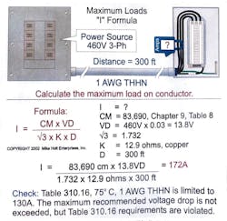
I = (CM × VD) ÷ (1.732 × K × D)
CM = 83,690 (1 AWG, Chapter 9, Table 8)
VD = 460V × 0.03 = 13.8V
K = 12.9 ohms, copper
D = 300 ft
I = (83,690 CM × 13.8V) ÷ (1.732 × 12.9 ohms × 300 ft) = 172A
Note: The maximum load permitted on 1 AWG THHN at 75°C is 130A [110.14(C) and Table 310.16].
The NEC doesn't require you to do voltage drop calculations because they aren't involved in issues of safety, but that doesn't mean they aren't important. A system that meets NEC requirements may not be efficient in terms of power consumption or optimum in terms of equipment longevity and performance. As the old saying goes, “Wire is cheap, but performance loss is costly.” First, ensure that your system meets NEC requirements. Then look at it for voltage drop so you get the right cost tradeoffs between performance and cost.
About the Author

Mike Holt
Mike Holt is the owner of Mike Holt Enterprises (www.MikeHolt.com), one of the largest electrical publishers in the United States. He earned a master's degree in the Business Administration Program (MBA) from the University of Miami. He earned his reputation as a National Electrical Code (NEC) expert by working his way up through the electrical trade. Formally a construction editor for two different trade publications, Mike started his career as an apprentice electrician and eventually became a master electrician, an electrical inspector, a contractor, and an educator. Mike has taught more than 1,000 classes on 30 different electrical-related subjects — ranging from alarm installations to exam preparation and voltage drop calculations. He continues to produce seminars, videos, books, and online training for the trade as well as contribute monthly Code content to EC&M magazine.