In Part 1, we looked at specific types of commercial loads. Let’s use some examples to show yet another difference in demand factors. If you were to watch daily operations at a marina [555.12], you’d see why its demand factors differ from those for, say, hotel rooms. As you can imagine, the usage is very different. The demand factors must change to make sense for the application.
The NEC permits a demand factor for the marina receptacle outlets that provide shore power for boats. Table 555.12 demand factors are based on the number of receptacles on the feeder. The receptacles must also be balanced between the phases to determine the number of receptacles on any given line.
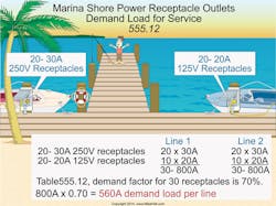
It’s helpful to look at an example problem. What’s the demand load for a 120/240V, single-phase service required for a marina with twenty 30A, 250V receptacles and twenty 20A, 125V receptacles (Fig. 1)?
Related
The demand load is based on the number of receptacles, so distribute the receptacles equally on each line to determine the connected load per line. All the 250V receptacles connect between L1 and L2, but for the 125V receptacles, half are put on L1 and the other half on L2. So the split results in the following breakdown.
Line 1: Twenty 30A, 250V receptacles and ten 20A, 125V receptacles for a total of 30 receptacles, or 800A.
Line 2: Twenty 30A, 250V receptacles and ten 20A, 125V receptacles for a total of 30 receptacles, or 800A.
As noted in Table 555.12, 30 receptacles calls for a demand factor of 70%.
Demand load per line = connected load per line × demand factor = [(20 × 30A) + (10 × 20A)] × 0.70 = 800A × 0.70 = 560A per line.
Optional method
Let’s move on to yet another wrinkle: the optional method. You can use this to calculate the service load for a new restaurant that has electric space heating or electric air-conditioning (or both) [220.88].
Step 1: Determine the total connected load. Add the nameplate rating of all loads at 100%; include both the air-conditioning and heat load [Table 220.88 Note].
Step 2: Apply the demand factors from Table 220.88 to the total connected load calculated in Step 1.
Let’s run through an example problem to clarify these points.
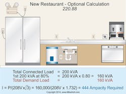
What is the service conductor ampacity required for an all-electric restaurant (120/208V, 3-phase) that has a total connected load of 200kVA (Fig. 2)?
Total connected load = 200kVA
You calculate the first 200kVA at 80%.
200kVA × 0.80 = 160kVA
Total demand load = 160kVA
I = VA ÷ (E x 1.732)
I = 160,000VA ÷ (208V x 1.732)
I = 160,000VA ÷ 360V
I = 444A
To determine the ungrounded service conductor size, if installed parallel in two raceways:
444A ÷ 2 raceways = 222A
A quick check of Table 310.15(B)(16) shows that a 4/0 AWG conductor would work in this situation, as it’s rated 230A at 75°C.
Welders
Commercial applications also include special loads, not just special occupancies. A welder is a very specialized load. Electric welders operate by either creating an electric arc between two surfaces or heating a metal rod until it melts. Each technique produces high momentary current draws.
The supply conductors for arc welders must have an ampacity at least that of the welder nameplate rating [630.11(A)]. If the nameplate rating isn’t available, the supply conductors must have an ampacity at least that of the rated primary current as adjusted by the multiplier in Table 630.11(A), based on the duty cycle of the welder.
Once again, let’s run through an example problem to clarify these points.
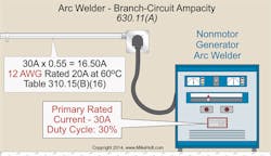
A nonmotor-generator arc welder has a primary current rating of 30A with a duty cycle of 30%. What’s the minimum size branch circuit conductor for the welder (Fig. 3)?
Demand load = primary rating × multiplier
A quick check of Table 630.11(A) shows that a nonmotor generator with a duty cycle of 30% has a multiplier of 0.55. Therefore,demand load = 30A × 0.55 = 16.50A
A quick check of Table 310.15(B)(16) shows that a 12 AWG conductor is rated 20A at 60°C [110.14(C)(1)(a)].
Groups of welders
Conductors that supply a group of resistance welders must have an ampacity that’s at least the sum of the value determined using Sec. 630.31(A)(2) for the largest welder in the group, plus 60% of the values determined for all remaining welders [630.31(B)].
Here’s another example problem to help clarify these points.
What’s the minimum size conductors that supply five 30A resistance welders with a duty cycle of 30%?
Demand load = primary rating × multiplier
A quick check of Table 630.31(A)(2) shows that an electric welder with a duty cycle of 30% has a multiplier of 0.55. As noted in Sec. 630.31(B), “The ampacity of conductors that supply two or more welders shall not be less than the sum of the value obtained in accordance with 630.31(A) for the largest welder supplied and 60% of the values obtained for all the other welders supplied.” Therefore,
Welder 1: 30A × 0.55 = 16.50A × 100% = 16.50A
Welder 2: 30A × 0.55 = 16.50A × 60% = 9.90A
Welder 3: 30A × 0.55 = 16.50A × 60% = 9.90A
Welder 4: 30A × 0.55 = 16.50A × 60% = 9.90A
Welder 5: 30A × 0.55 = 16.50A × 60% = 9.90A
Total demand load = 56.10A
A quick check of Table 310.15(B)(16) shows that a 4 AWG conductor is rated 70A at 60°C [110.14(C)(1)(a)].
Putting it all together
This example problem helps put various calculation pieces together in a typical light industrial situation.
Calculate the service size for a light industrial manufacturing building with the following loads:
- Lighting load of 11,600VA, comprised of electric-discharge luminaries operating at 277V.
- Twenty-two 20A, 125V receptacle outlets on general-purpose branch circuits, supplied by a separately derived system (since system for building is 480V 3-phase).
- Three nonmotor generator arc welders (23A, 480V, 60% duty).
- Air compressor, 460V, 3-phase, 5 hp.
- Grinder, 460V, three-phase, 1½ hp.
- Three continuous use industrial process dryers, 480V, 3-phase, 15kVA each.
Step 1: Determine the noncontinuous loads and motor loads.
The noncontinuous and motor loads can be combined [430.24].
Noncontinuous loads
Receptacle load [220.44]: 22 receptacles at 180VA = 3,960VA
Welder load [630.11(A) and Table 630.11(A)]. A multiplication factor of 0.78 is allowed for 60% duty cycle welders.
Each welder: 480V × 23A × 0.78 = 8,600VA
Welder demand factors for 3 welders: [630.11(B)]
First welder = 100%
Second welder = 100%
Third welder = 85%
8,600VA × 100% = 8,600VA
8,600VA × 100% = 8,600VA
8,600VA × 85% = 7,320VA
Total welder demand load = 24,510VA
Total noncontinuous loads (receptacles and welders) = 28,470VA
Motor loads [430.24 and Table 430.250]
Air compressor: 5 hp FLC = 7.60A
[Table 430.250] 480V × 7.60A × 1.732 = 6,318VA
Grinder: 1½ hp FLC = 3A [Table 430.250] 3A × 480V × 1.732 = 2,494VA
Largest motor, additional 25%: 6,310VA × 25% = 1,578VA
Total motor loads = 10,390VA
Therefore, the total noncontinuous loads and the motor loads [430.24] = 38,860VA
Step 2: Determine the continuous loads.
General lighting = 11,600VA
Three industrial process dryers,15kVA each = 45,000VA
Total load = 56,600VA
Total continuous load at 125% = 56,600VA × 1.25 = 70,750VA
Step 3: Determine the overcurrent protection [215.3].
The overcurrent device must be sized at 125% of the continuous loads, plus the noncontinuous loads:
Noncontinuous loads = 38,860VA
Continuous loads = 70,750VA
Total VA = 109,610VA
Step 4: Convert to amperes to size the overcurrent device:
I = VA ÷ (E x 1.732)
I = 109,610VA ÷ (480V × 1.732)
I = 109,610VA ÷ 831V
I = 132A
Select the overcurrent device based on the next size up rule [240.4(B)]. The proper choice is a 150A device [240.6].
A quick check of Table 310.15(B)(16) reveals that a 1/0 AWG conductor has an ampacity of 150A at 75°C [110.14(C)(1)(b). Keep in mind that parallel conductors must comply with Sec. 310.10(H).
Keeping commercial calculations Code compliant
With so many application-specific requirements, commercial calculations could become confusing. Some final thoughts here can help you avoid that.
The calculations used to size feeders and service conductors for commercial installations don’t include the same demand factors allowed for dwelling units. The nature of nondwelling occupancies doesn’t create the same kinds of diversity found in homes and apartment buildings.
Article 220 isn’t the only Article that contains service calculation requirements. For example, you’ll also find them in Art. 550 (mobile home parks), Art. 555 (marinas), Art. 630 (electric welders), and Art. 430 (motors). When performing commercial service calculations, be careful to look at all components of the installation to determine if some other Article applies to your installation.
You can apply certain demand factors to commercial services. When dealing with individual branch circuits and feeders for continuous loads, remember to use a 125% multiplier for the ungrounded conductors. This carries over to the continuous duty portions of loads when determining the actual feeder and service conductors for commercial occupancies.
You can size the neutral conductor at 100% of the continuous and noncontinuous loads for branch circuits and feeders when it’s not connected to an overcurrent device [210.19(A)(1), Exception No. 2 and 215.2(A)(1), Exception No. 2]. Optional calculations are allowed for some commercial installations, so be certain to see if your application is one of those.
Holt is the owner of Mike Holt Enterprises, Inc. in Leesburg, Fla. He can be reached at www.mikeholt.com.
About the Author

Mike Holt
Mike Holt is the owner of Mike Holt Enterprises (www.MikeHolt.com), one of the largest electrical publishers in the United States. He earned a master's degree in the Business Administration Program (MBA) from the University of Miami. He earned his reputation as a National Electrical Code (NEC) expert by working his way up through the electrical trade. Formally a construction editor for two different trade publications, Mike started his career as an apprentice electrician and eventually became a master electrician, an electrical inspector, a contractor, and an educator. Mike has taught more than 1,000 classes on 30 different electrical-related subjects — ranging from alarm installations to exam preparation and voltage drop calculations. He continues to produce seminars, videos, books, and online training for the trade as well as contribute monthly Code content to EC&M magazine.


