Branch Circuits – Part 1
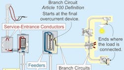
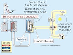
The distinction between a branch circuit and a feeder can be a source of confusion for many Code users. The first step in eliminating this confusion is to understand that the NEC defines a branch circuit as “the conductors between the branch circuit final overcurrent device protecting the circuit and the outlets” (such as receptacles or lights) [Art. 100], as shown in Fig. 1. By contrast, a feeder circuit runs from the service equipment, the source of a separately derived system, or other power supply to (rather than from) the final branch circuit overcurrent device.
The size of the circuit breaker installed on a branch circuit, not the conductor size, determines the rating of the circuit. Therefore, if the conductor size is increased to accommodate for voltage drop or for ampacity adjustment or correction purposes, the rating of the circuit remains the same as the circuit breaker size supplying it [210.3].
You’ll find branch circuit requirements for conductor sizing, overcurrent protection, identification, GFCI protection, receptacles, and lighting outlets in Art. 210. Other Articles may apply to your installation; you’ll find those listed in 210.2.
Multiwire branch circuits
A multiwire branch circuit basically consists of two or more ungrounded conductors that share a neutral. All conductors of a multiwire branch circuit must originate from the same panelboard [210.4(A)].
For personnel safety, each multiwire branch circuit must have a means to simultaneously disconnect all ungrounded conductors at its origin [210.4(B)]. If that origin is two or more breakers, you can provide this disconnect by using single-pole circuit breakers with handle ties identified for the purpose [240.15(B)(1)].
Multiwire branch circuits can supply only line-to-neutral loads [210.4(C)], except that a multiwire branch circuit can also supply:
- An individual piece of line-to-line utilization equipment, such as a range or dryer [210.4(C) Ex 1].
- Both line-to-line and line-to-neutral loads if the circuit is protected by a device such as a multipole circuit breaker with a common internal trip that opens all ungrounded conductors of the multiwire branch circuit simultaneously under a fault condition [210.4(C) Ex 2].
In multiwire branch circuits, the continuity of the neutral conductor must not be interrupted by the removal of a wiring device. In these applications, the neutral conductors must be spliced together at every device providing a pigtail to terminate to the wiring device [300.13(B)]. The opening of the ungrounded conductors, or the neutral conductor of a 2-wire circuit during the replacement of a device, doesn’t cause a safety hazard, so pigtailing these conductors isn’t required [110.14(B)]. Caution: If the continuity of the neutral conductor of a multiwire circuit is interrupted (opened), the resultant over- or undervoltage can cause a fire and/or destruction of electrical equipment.
The ungrounded and neutral conductors of a multiwire branch circuit must be grouped together using cable ties or similar means at the point of origination [210.4(D)]. These conductors are not required to be grouped if they are contained in a single raceway or cable unique to that circuit, making the grouping obvious.
If the ungrounded conductors of a multiwire circuit don’t terminate to different phases or lines, the currents on the neutral conductor will add instead of canceling each other out, possibly overloading the neutral conductor.
Identification
Equipment grounding conductors are allowed to be bare, covered, or insulated. Insulated equipment grounding conductors size 6 AWG and smaller must have a continuous outer finish — either green or green with one or more yellow stripe(s) [250.119]. If installing equipment grounding conductors
4 AWG and larger, you can permanently reidentify the insulation with green markings or tape, or strip the insulation off of the conductor. This reidentification must be done at every point where the conductor is accessible [250.119(A)].
Identify the neutral (“grounded”) conductor per 200.6. If 6 AWG or smaller, it must be white, gray, or some color other than green with white stripes along its entire length. For 4 AWG and larger, the same means of identification can be used, or it is allowed to use white or gray tape at terminations.
If you have more than one voltage system, then for each ungrounded conductor [210.5(C)]:
- Identify it by phase and system at all termination, connection, and splice points.
- Identification can be by color coding, marking tape, tagging, or other means approved by the AHJ.
- Document the method of identification in a manner that’s readily available or permanently posted at each branch circuit panelboard.
Voltage limitations
In dwelling units, the voltage between conductors must not exceed 120V, nominal, when they supply the terminals of [210.6(A)] luminaires or cord- and plug-connected loads less than ¼ hp or less than or equal to 1,440VA [21.6].
Multiple branch circuits
If two or more branch circuits supply devices (or equipment) on the same yoke, a means must be provided at the circuit’s point of origin to disconnect simultaneously all ungrounded conductors that supply those devices [210.7].
GFCI for dwelling units
Install a GFCI at a readily accessible location for all 15A and 20A, 125V receptacles located in the following locations [210.8(A)]:
- Bathrooms.
- Garages and accessory buildings.
- Outdoors.
- Crawl spaces.
- Unfinished basements.
- Serving kitchen countertops.
- Within 6 ft of the outside edge of sinks, in addition to the requirements for kitchen sinks.
- Boathouses.
Also:
- Each dwelling unit of a multifamily dwelling that has its own grade level entrance must have at least one accessible GFCI-protected receptacle at 6½ ft or less above grade [210.52(E)(2)].
- Balconies, decks, and porches attached to the dwelling unit and accessible from inside the dwelling must have at least one GFCI-protected receptacle outlet accessible from the balcony, deck, or porch [210.52(E)(3)].
However, you don’t need GFCI protection for a receptacle supplied by a branch circuit dedicated to fixed electric snow-melting, deicing, pipeline heating, or vessel heating equipment, if:
- The receptacle isn’t readily accessible, and
- The equipment or receptacle has ground-fault protection of equipment (GFPE) [426.28 and 427.22].
GFCI for non-dwelling units
Install GFCI at a readily accessible location for all 15A and 20A, 125V receptacles in any of the following commercial/industrial locations [210.8(B)]:
- Bathrooms.
- Kitchens (not required for hard-wired equipment).
- Rooftops (A 15A or 20A, 125V receptacle must be installed within 25 ft of heating, air-conditioning, and refrigeration equipment [210.63]).
- Outdoors.
- Sinks (except in laboratories where removal of power would introduce a greater hazard or in patient bed locations of general care or critical care areas of health care facilities).
- Indoor wet locations.
- Locker rooms with associated showering facilities.
- Garages (where electrical diagnostic equipment, electrical hand tools, or portable lighting equipment are to be used).
- Boat hoists.
You don’t need GFCI protection for a receptacle supplied by a branch circuit dedicated to fixed electric snow-melting, deicing, pipeline heating, or vessel heating equipment, if:
- The receptacle isn’t readily accessible, and
- The equipment or receptacle has ground-fault protection of equipment (GFPE) [426.28 and 427.22].
Note: The list of GFCI requirements in 210.8 is not all-inclusive. For example, there are also GFCI requirements for cord- and plug-connected vending machines and electric drinking fountains in Art. 422 [422.51 and 422.52].
Number of circuits
There’s no maximum number of receptacles on a dwelling unit circuit. But how do you determine the minimum number of circuits for general lighting and general-use receptacles? Divide the total calculated load in amperes by the ampere rating of the circuits used [210.11]. See Example D1(a) in Annex D. If you calculate the total load based on VA/square foot, ensure the individual loads are evenly proportioned among multioutlet branch circuits within the panelboard.
Required circuits
It’s not just the total number of outlets that matters. The NEC also requires certain types of circuits in specific places in addition to the minimum requirements based on the VA/square foot calculation.
A dwelling unit kitchen, dining room, breakfast room, pantry, or similar area must have at least two 20A, 120V small-appliance receptacle branch circuits [for the 15A or 20A receptacle outlets required in these rooms by 210.52(B)]. These circuits can’t supply other outlets [210.52(B)(2)], including those for lighting. You can use one 3-wire multiwire circuit or two separate 120V circuits [210.4(A)]. At least two small-appliance circuits must supply the receptacles above the countertops [210.52(B)(3)].
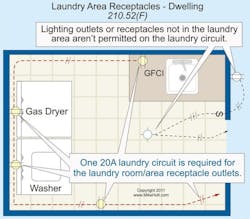
Provide one 20A, 120V branch circuit for the receptacle outlets required by 210.52(F) for the laundry room. The 20A laundry room receptacle circuit can supply more than one receptacle in the laundry room. This receptacle can’t supply other outlets, such as the laundry room lighting or receptacles in other rooms (Fig. 2).
GFCI protection isn’t required for 15A and 20A, 125V receptacles in a laundry room, unless they’re within 6 ft of a sink [210.8(A)(7)].
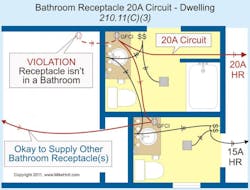
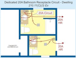
Provide one 20A, 120V branch circuit for the receptacle outlets required by 210.52(D) for a dwelling unit bathroom or multiple bathrooms. This circuit can’t supply other outlets, such as receptacles in rooms other than bathrooms or lighting outlets [210.11(C)(3)], as shown in Fig. 3.
An alternate method allows this circuit to supply all of the outlets in a single bathroom, including lighting and fans, if no single load fastened in place is rated more than 10A [210.11(C)(3) Ex and 210.23(A)], as shown in Fig. 4.
This gives you a good start on understanding branch circuit requirements. In our next issue, we’ll look at some additional branch circuit requirements, starting with arc fault circuit interrupters (AFCIs).
