Article 810: Radio and Television Equipment
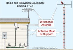
Article 810 provides installation requirements for transmitter and receiver equipment as well as the associated wiring and cabling (Fig. 1). Article 810 applies to:
-
VHF/UHF antennas, which receive local television signals.
-
Satellite antennas, also called satellite dishes.
-
Roof-mounted antennas for AM/FM/XM radio reception.
-
Amateur radio transmitting and receiving equipment, including HAM radio equipment (a noncommercial communications system).
Requirements for all antenna systems. The first three kinds of installations in the bulleted list above involve receiving signals. The fourth also involves transmitting, which is why amateur radio installations have additional requirements over those for receiving antenna systems installations — we'll address those last.
Follow the requirements of Chapters 1 through 4 when wiring from the power source to Art. 810 equipment. Note that wiring for audio equipment must comply with Art. 640.
Install coaxial cables per Art. 820 [810.3], if they connect antennas to equipment. Coax cable beyond the point of entry falls under Art. 820 [810.4] (Fig. 2). You will find the grounding requirements for antenna cables in 810.20(C) and 810.21.
Outdoor antennas and lead-in conductors must be securely supported, and the lead-in conductors must be securely attached to the antenna [810.12]. Don't attach outdoor antennas to the electric service mast [230.28]. Keep outdoor antennas and lead-in conductors at least 2 feet from exposed electric power conductors, to avoid the possibility of accidental contact [810.13].
Ground outdoor masts (and metal structures that support antennas) in accordance with 810.21 [810.15]. If an antenna mast is within 5 feet of a swimming pool, bond it to the equipotential bonding grid of the pool [680.26(B)(5)].
Antenna discharge unit. Provide a listed antenna discharge unit for each lead-in conductor of an outdoor antenna. Locate discharge units as close to the point of entrance (inside or outside) as you can, but not near combustible material.
Nothing can prevent damage from a direct lightning strike, but grounding with proper surge protection can help reduce damage from nearby lightning strikes. Grounding helps prevent voltage surges (caused by static discharge or nearby lightning strikes) from reaching the center conductor of the lead-in coaxial cable.
Because the antenna is outdoors, wind creates a static charge on the antenna and on the cable attached to it. This charge can build up on both antenna and cable until it jumps across an air space, often passing through the electronics inside the “low noise block down converter feed” horn or receiver. Grounding helps to dissipate this static charge.
Ground the antenna mast [810.15] and antenna discharge units [810.20(C)] as specified in 810.21(A) through 810.21 (K) (Fig. 3), which we'll discuss next.
(A) Material. The grounding conductor to the electrode [810.21(F)] must be copper or other corrosion-resistant conductive material. It can be stranded or solid.
(B) Insulation. The grounding conductor can be insulated or bare.
(C) Supports. The grounding conductor must be securely fastened in place.
(D) Protection against physical damage. The grounding conductor must be guarded from physical damage. If the grounding conductor is in a metal raceway, bond each end of the raceway to the grounding conductor. Installing the grounding conductor in a nonmetallic raceway, when the authority having jurisdiction (AHJ) judges that physical protection is required, is a better practice than using a metal raceway.
(E) Run in straight line. The grounding conductor must be run in as straight a line as practicable. Lightning doesn't like to travel around corners or through loops — it tends to jump across them or from them to nearby objects.
(F) Electrode. The grounding conductor must terminate to the nearest accessible:
-
Structure grounding electrode system [250.50].
-
Interior metal water piping system, within 5 feet from its point of entrance [250.52(A)(1)].
-
Service bonding means [250.94].
-
Metallic service raceway.
-
Service equipment enclosure.
-
Grounding electrode conductor or the grounding electrode conductor metal enclosure.
(G) Inside or outside building. The grounding conductor can be run either inside or outside the building.
(H) Size. The grounding conductor must not be smaller than 10 AWG copper or 17 AWG copper-clad steel or bronze. Copper-clad steel or bronze wire (17 AWG) is often molded into the jacket of the coaxial cable to simplify the grounding of the satellite dish by eliminating the need to run a separate ground wire to the dish [810.21(F)(1)].
(J) Bonding of electrodes. If a ground rod is installed to serve as the ground for the radio and television equipment, you must connect it to the power grounding electrode system with a minimum 6 AWG conductor. The bonding of separate system electrodes reduces voltage differences that may develop between them.
(K) Electrode connection. Termination of the grounding conductor must be by exothermic welding, listed lug, listed pressure connector, or listed clamp. Grounding fittings that are concrete-encased or buried in the earth must be listed for direct burial and marked “DB” [250.70].
Receiving equipment. If lead-in conductors are attached to buildings, install them in a way that prevents them from swinging closer than 2 feet to the conductors of circuits of 250V (or less) or closer than 10 feet to the conductors of circuits of more than 250V. Keep all lead-in conductors at least 6 feet from lightning protection conductors [810.18].
In addition, keep in mind that:
-
Underground antenna lead-in conductors must maintain a separation not less than 12 inches from power conductors [810.18(A)].
-
Indoor antenna and lead-in conductors must not be less than 2 inches from light and power conductors [810.18(B)].
For the two preceding requirements, you don't need separation if you have installed the lead-in conductors or the power conductors in a raceway or cable armor. Indoor antenna lead-in conductors can be in the same enclosure with power conductors where separated by an effective, permanently installed barrier.
So exactly how big must the antenna conductor be? That depends on how long the conductor is and what it's made of. If the conductor is [Table 810.16(A)]:
-
Less than 35 feet long — use 19 AWG copper or aluminum alloy or use 20 AWG copper-clad steel, bronze, or other high-strength material.
-
More than 35 feet long but less than 150 feet long — use 14 AWG copper (or 14 AWG aluminum alloy) or use 17 AWG copper-clad steel, bronze, or other high-strength material.
-
Longer than 150 feet — use 12 AWG copper (or 14 AWG aluminum alloy) or use 14 AWG copper-clad steel, bronze, or other high-strength material.
Transmitting (amateur radio). Amateur radio has additional requirements beyond those for receiving equipment, because of an additional function: transmitting. Thus, if the installation is an amateur radio system, it must comply with 810, Part III (810.51 through 810.58).
Obviously, the antenna conductors must be larger if you are also transmitting. If the conductors are longer than 150 feet, use either 10 AWG hard-drawn copper or 12 AWG copper-clad steel, bronze, or other high-strength material. If the length is under 150 feet, you can use 14 AWG in any of the aforementioned materials [Table 810.52].
With receiving installations, you can mount the antenna lead-in conductors on the surface of the building. But with amateur radio, the antenna lead-in conductors must be firmly mounted at least 3 inches away from the surface of the building [810.54]. If the lead-in conductors are enclosed in a continuous metallic shield (coaxial), you can secure them directly to the building structure [810.54 Ex].
As with receiving systems, each lead-in conductor from an amateur radio outdoor antenna must be provided with a listed antenna discharge unit (or other suitable means that drain static charges from the antenna system), except where:
-
Protected by a continuous metallic shield that is permanently and effectively grounded.
-
The antenna is permanently and effectively grounded.
Ground the antenna mast [810.15] and antenna discharge unit [810.57] as specified in 810.21(A) through (K), just as with the receiving stations. However, the operating grounding conductor for amateur radio installations must not be smaller than 14 AWG copper or equivalent [810.58(C)].
In general, what you are trying to do is keep the antennas from picking up anything other than radio or television signals. That means providing some space from other conductors to prevent induced voltage, bonding the mast and other metallic objects to prevent differences in potential, and properly grounding to protect against lightning-induced surges. You're still going to apply Chapter 1 through 4 requirements to the rest of the system.
Sidebar: Article 810 Key Points
-
Prevent contact with conductors of other systems.
-
Don't attach antennas or other equipment to the service-entrance power mast.
-
If the mast isn't grounded properly, voltage surges caused by nearby lightning strikes can destroy it. Keep the grounding conductor straight, and protect it from physical damage.
-
If the mast isn't bonded properly, you risk flashovers and possible electrocution. Because bonding prevents a difference of potential between metallic objects and other conductive items, Art. 810 provides several different bonding requirements.
-
Because clearances are critical, Art. 810 provides extensive clearance requirements.
About the Author

Mike Holt
Mike Holt is the owner of Mike Holt Enterprises (www.MikeHolt.com), one of the largest electrical publishers in the United States. He earned a master's degree in the Business Administration Program (MBA) from the University of Miami. He earned his reputation as a National Electrical Code (NEC) expert by working his way up through the electrical trade. Formally a construction editor for two different trade publications, Mike started his career as an apprentice electrician and eventually became a master electrician, an electrical inspector, a contractor, and an educator. Mike has taught more than 1,000 classes on 30 different electrical-related subjects — ranging from alarm installations to exam preparation and voltage drop calculations. He continues to produce seminars, videos, books, and online training for the trade as well as contribute monthly Code content to EC&M magazine.