Should you install equipment grounding conductors (EGCs)? Yes and no. The title of Art. 250, Part VI is “Equipment Grounding and Equipment Grounding Conductors,” but Part VI doesn’t provide any grounding requirements. It does provide equipment bonding (see Bonding or Grounding?) requirements. For the sake of (current) convention, we’ll use the technically incorrect (and misleading) term “equipment grounding.” But we (and the NEC) really mean “bonding.”
What’s an EGC? Section 250.118 identifies 14 items that can be used as an EGC. We’ll focus on 250.118(1), which is where a wire (or bus bar) is used as the EGC.
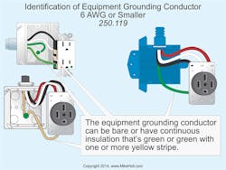
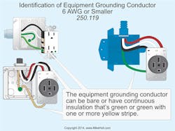
So others can identify your EGCs that aren’t bare, use conductors with a continuous green outer finish. Alternatively, this outer finish can be green with one or more yellow stripes [250.119]. Except for three special cases, you can’t use such conductors as ungrounded or neutral conductors (Fig. 1.)
The three special cases where green insulation can be used for an ungrounded conductor are:
1) Power-limited, Class 2 or Class 3 cables, power-limited fire alarm cables, or communications cables containing circuits operating at less than 50V [250.20(A) and 250.112(I)].
2) Flexible cords without an EGC (the outer jacket of the cord can be green).
3) Ungrounded signal conductors for traffic signal control and traffic signal indicating heads. The circuit must still include an EGC and if it’s of the wire type, it must be bare or green with one or more yellow stripes.
Prior to the 2014 NEC, the first special case was the only one, and it was the Exception to 250.119. Now it’s Exception No. 1, followed by Exception No. 2 and Exception No. 3.
Exception No. 2 (flexible cords) seems reasonable, as a 2-conductor cord isn’t an EGC, even if it’s green.
The traffic signal industry wanted this new Exception No. 3. Green isn’t an EGC for traffic signals; it’s the signaling conductor that controls the green traffic light.
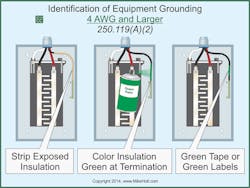
When installing insulated EGCs 4 AWG or larger, you have the option of permanently reidentifying them at every point where the conductor is accessible [250.119(A)(1)].
EGC identification must encircle the conductor by [250.119(A)(2)]: (Fig. 2).
a) Removing the insulation at termination.
b) Coloring the insulation green at termination.
c) Marking the insulation at termination with green tape or green adhesive labels.
EGC as grounding electrode conductor (GEC)
The 2011 NEC added a ban on using an EGC as a GEC. The 2014 NEC added an Exception that essentially nullifies the ban. Now you can use an EGC as a GEC if it’s of the wire type and meets all of the rules for both [250.121].
Most inspectors allowed a conductor to serve as the EGC and the GEC if it met the rules for both. With the new Exception, we’re back to where we were in 2008.
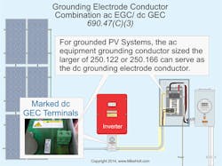
For PV systems, 690.47(C) permits a combined EGC/GEC if sized to the larger of 250.122 or 250.166 and installed per 250.64(E) (Fig. 3).
EGC sizing
You might want to increase the size of ungrounded conductors to accommodate conductor voltage drop, harmonic current heating, short circuit rating, or future capacity. But what does this mean for your EGC?
For a long time, the NEC has said that if you increase the size of the ungrounded conductors, you must also increase the size of the EGC. That gives rise to a question. When you increase the size of the ungrounded conductors, what size EGC should you use? Would that be the minimum size required to satisfy the NEC, or would that be the size you need to reduce voltage drop or accommodate harmonics?
The 2014 NEC clarifies the rule on increasing the size of the EGC (although you may have to read it several times to agree). If you increase the size of ungrounded conductors from the minimum ampacity required for the load, you must proportionately increase the size of your wire type EGCs. Base the increase on the circular mil area of the ungrounded conductors [250.122(B)].
With the 2014 NEC, it’s clear that adjustments for conditions of use (e.g., ampacity adjustment for the number of conductors in a raceway, temperature correction factors) don’t count as “increases in size.”
The adjustments don’t count because you don’t get the correct conductor ampacity until after you’ve adjusted for the conditions of use. If you make a conductor larger due to ampacity adjustment or temperature correction, it’s still the minimum ampacity required by the Code.
But if you make the conductor larger due to voltage drop or something else outside the NEC requirements, you increased its size above the minimum ampacity for the load. And that would be an “increase in size.”
Replacing nongrounding receptacles
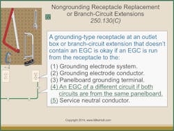
If you replace a nongrounding receptacle with a grounding-type receptacle from an outlet box that doesn’t contain an EGC, you must connect the grounding contacts of the receptacle to one of the following [250.130(C)] (Fig. 4).
• Grounding electrode system [250.50].
• Grounding electrode conductor.
• Panelboard equipment grounding terminal.
• An EGC that’s part of a different circuit, if both circuits originate from the same panel.
• Service neutral conductor.
Can you replace a nongrounding-type receptacle with a grounding-type receptacle and not connect the grounding to an EGC? Yes, if the receptacle is GFCI-protected and marked per 406.4(D)(2) [250.130(C) Informational Note].
Bonding
Correctly applying the bonding requirements is essential to a safe and reliable installation. Yet it’s here that confusion reigns supreme.
Bringing an installation into compliance with Part V of the NEC often solves previously “mysterious” problems. Common symptoms of noncompliance include power quality problems, “inexplicable” touch potential shocks to personnel, and motor bearing failures. Confusion about bonding requirements is usually why those symptoms appeared in the first place.
Part V begins with subsection 90 and ends with subsection 106. The 2014 changes begin with subsection 100, which addresses bonding in hazardous locations. The requirement now refers to classified location definitions in 500.5, 505.5, and 506.5. The new Informational Note reminds Code users to see the relevant Chapter Five bonding requirements (501.30, 502.30, 503.30).
Regardless of the circuit voltage, you must maintain the electrical continuity of metal parts of equipment and raceways in hazardous (classified) locations. You do this by bonding, which eliminates differences of potential. Those differences can cause ignition via arc flash.
Another 2014 change to Part V is the addition of Table 250.102(C)(1). This table addresses supply-side bonding jumpers, main bonding jumpers, system bonding jumpers, and service neutral conductors. Size your supply-side jumpers per this table. If the ungrounded supply conductors are paralleled in two or more raceways or cables, size the supply-side bonding jumper for each raceway or cable based on the size of the largest ungrounded conductors in each raceway or cable [250.102].
This table is a near-perfect reproduction of Table 250.66. Despite being named “Grounding Electrode Conductor for AC Systems,” Table 250.66 always served many different roles. These included sizing the main bonding jumper, system bonding jumper, supply-side bonding jumper, and minimum service neutral conductor. All of these other than the GEC must carry fault current back to the source, and thus are very different from the GEC. It makes sense to create a new table for these items.
Why the lack of significant technical changes to the bonding requirements? The main concept behind bonding is simple: Create a low-impedance path between metallic objects, such that you eliminate differences of potential. The execution hasn’t changed much. With each Code cycle, the changes to Part V typically involve clarification rather than something of a technical nature.
One aspect of clarification that still needs to permeate the NEC (especially Art. 250) is consistent use of the words “bonding” and “grounding.” An example is the EGC. It’s a bonding path, not a grounding path.
Avoiding confusion
Article 250 is big, and it still needs extensive revision for its wording to agree with Art. 100 definitions. This can make using it tricky and time-consuming. You’re under pressure to get the job done, but you need to be confident you’re not installing a slew of Art. 250 violations. What’s the solution?
Table 250.1 is a sort of “road map” for Art. 250, so start there. You do grounding only on the supply side. If you’re doing only load side work, your requirements will be in Parts I, IV, V, VI, and VII. These also cover supply work (which includes bonding), but the other Parts are where you’ll find your grounding requirements.
The acid test for bonding is this: If a voltage exists between two metallic objects (e.g., a panel and an enclosure), you’ve got a bonding deficiency. Eliminate it with a run of wire and the appropriate connectors.
Holt is the owner of Mike Holt Enterprises, Inc. in Leesburg, Fla. He can be reached at www.mikeholt.com.
SIDEBAR: Bonding or Grounding
Article 100 tells us that grounding is a connection to the earth, while bonding is a connection that establishes electrical continuity and conductivity. You ground with dirt, you bond with copper or aluminum conductors or, in some cases, metallic raceways.
On the load side, grounding serves no technical purpose (but bonding is extremely important). On the supply side, proper grounding is essential for lightning protection, and you need bonding to prevent problems such as flashover.
About the Author

Mike Holt
Mike Holt is the owner of Mike Holt Enterprises (www.MikeHolt.com), one of the largest electrical publishers in the United States. He earned a master's degree in the Business Administration Program (MBA) from the University of Miami. He earned his reputation as a National Electrical Code (NEC) expert by working his way up through the electrical trade. Formally a construction editor for two different trade publications, Mike started his career as an apprentice electrician and eventually became a master electrician, an electrical inspector, a contractor, and an educator. Mike has taught more than 1,000 classes on 30 different electrical-related subjects — ranging from alarm installations to exam preparation and voltage drop calculations. He continues to produce seminars, videos, books, and online training for the trade as well as contribute monthly Code content to EC&M magazine.
