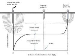
Along with the development of new instrumentation, the test procedure itself was also standardized. By “walking” the potential probe toward the current probe and graphing the measurements, the end-user could develop a profile that reliably indicated the ground electrode's resistance. This test procedure is otherwise known as the “Fall of Potential” method and is described by ANSI/IEEE “Guide for Measuring Earth Resistivity, Ground Impedance, and Earth Surface Potentials of an Earth System” (ANSI/IEEE Standard 81).
Various other popular test methods, such as Slope, 62% Rule, and Intersecting Curves, were all derived from the Fall of Potential method (Fig. 1), with slight modifications to deal with special situations or to improve productivity. However, all of these methods employ the same instrumentation. The good news is this instrumentation has been steadily improved in terms of convenience, safety, ease of operation, accuracy, and available features.
Stakeless method. During the last decade, a new technology appeared in the market, in the form of the clamp-on ground tester. This testing device was developed specifically for improving the speed and convenience of the ground test. The Fall of Potential test can be labor intensive and time consuming. Even the expedient methods still require you to string leads and drive probes. The clamp-on tester represented a quantum leap in convenience. Just clamp it over the ground rod and take a reading. However, this convenience is both an advantage and a drawback for the end-user.
Properly understood, the clamp-on ground tester can be an indispensable tool. But its simplicity can also lead to trouble. Many end-users tend to clamp around any convenient point and take away the reading without question. As a result, this method has become unwelcome by some in the industry. To be effective, the user of this piece of test equipment must be aware of its principle of operation, where it will and won't work, and the applications for which traditional methods only must be employed.
The clamp-on approach (Fig. 2) was derived from the original “shortcut” procedure (i.e. the “2-point” or “dead earth” test method). The shortcut test is made by simply connecting a piece of test equipment between the test electrode and a remote ground, and then measuring a loop resistance. The method is easy, but it loses accuracy because all the other elements in the loop are part of the measurement. It is fraught with the danger of inaccuracy because the remote probe must be of negligible resistance, which may not be the case. The clamp-on test avoids this problem by relying on multiple return paths, which are in parallel with each other. By the Law of Parallel Resistances, the return resistance virtually cancels out, and the tester measures only the resistance of the soil.
where, usually
The jaws of a clamp-on tester contain two windings. When clamped over a ground rod and energized, a CT in the tester induces a test current in the circuit via electromagnetic coupling. The current travels through the soil and returns to the rod (but more significantly the jaws of the tester), thus completing the circuit through all available system grounds. Since multiple parallel utility grounds, for instance, are normally plentiful, their total resistance is negligible, and the test measures principally the resistance of the intervening soil. The tester accurately measures the current flow, and the second winding in the jaws sense the voltage drop around the loop. Ohm's Law does the rest.
The clamp-on tester can be an enormous time saver, but unlike its traditional three-point counterpart, it cannot be used everywhere. The clamp-on tester should not be used in the following situations:
-
Commission new grounds, as they will not yet be connected to the utility power supply, and hence no return path exists for the test current.
-
Measure soil resistivity (electrical conductivity properties of the soil); this requires the use of a four-terminal tester.
-
Test any complex ground system where a metallic loop exists; test current will return through metal and not be forced into the soil. These include systems such as ring grounds, counterpoise, substation grounds, and various other multiple interconnected ground systems.
-
Perform any test where a client or third party require conformance to a reference standard; the clamp-on test method has not been incorporated into any independent standard.
On the other hand, you can use the clamp-on tester to:
Prior to about 15 years ago, the basic methodology for ground testing remained fundamentally unchanged since it was originally devised in the early 20th century. The end-user would use a test instrument and probes to first inject a current into the earth between a test electrode and a remote probe, measure the voltage drop caused by the soil to a designated point, and then use Ohm's Law to calculate the resistance. Initially, separate current sources and voltmeters were employed, and the calculation was done by hand. Soon, dedicated ground test instruments appeared on the scene to help reduce operator error and increase the speed and efficiency of the test.
-
Test installed grounds without having to disconnect them from the utility supply system.
-
Test any grounding electrode configuration where there is a return path that includes the earth.
-
Test the resistance of a single rod in a series or array.
-
Simultaneously perform a bonding test of the grounding conductor (necessary to complete the return path).
-
Check errant current flow to ground for operator safety and give an overview of ground system dynamics.
The bottom line. Looking at the big picture, both types of testing — traditional and clamp-on — have unique strengths. They are by no means competing or mutually exclusive technologies. For their effective use, you must understand their differences. Merely clamping on to any accessible point in an electrical grounding system does not constitute effective ground testing. A well-equipped ground-testing program will take advantage of both technologies.
Jowett is a senior applications engineer with Megger, Valley Forge, Pa.