The Basics of Bonding and Grounding Transformers

After a national arc-flash hazard analysis project was performed at eight recently constructed parts distribution warehouse sites for a Global 100 company as part of an OSHA Voluntary Protection Program (VPP), management found the results to be somewhat shocking.
During the data gathering process, Electrical Service Solutions, Inc., discovered more than 35 violations of the National Electrical Code (NEC) involving improper bonding and grounding of transformers. Violations ranged from system bonding jumpers that were missing, undersized, improperly terminated, and installed in two locations to grounding electrode conductors that were either missing, undersized, improperly terminated to the electrode, and/or connected to the separately derived system in a location other than where the system bonding jumper was connected. These findings reiterate the fact that a significant amount of confusion still remains in the industry on the topic of bonding and grounding of transformers. Let’s take a closer look at the areas where most of the misconceptions arise.
The effective ground-fault current path
To understand the concept of bonding and grounding for safety, the installer must know that for normal load current, short circuit current, or ground-fault current to flow, there must be a continuous circuit or path — and a difference of potential. The 2011 NEC defines the effective ground-fault current path as “an intentionally constructed, low-impedance electrically conductive path designed and intended to carry current under ground-fault conditions from the point of a ground fault on a wiring system to the electrical supply source and that facilitates the operation of the overcurrent protective device or ground-fault detectors on high-impedance grounded systems.” An effective ground-fault current path is an essential part of the overcurrent protection system.
- The path for ground-fault current must be electrically continuous and reliable.
- It must have adequate current-carrying capacity to conduct safely (both in magnitude and duration) any fault likely to be imposed on it.
- It must be of low impedance to facilitate the instantaneous operation of the overcurrent device in the ground-fault current path.
A ground-fault current path for a grounded separately derived system/transformer that doesn’t meet these criteria becomes a silent and often lethal source of electrical shock when a ground fault occurs. If an effective ground-fault current path isn’t established and a ground-fault occurs on the derived ungrounded circuit conductors of a transformer, ground-fault current will not flow; therefore, the operation of the overcurrent protection device in the ground-fault current path won’t be initiated. Electrical raceways, enclosures, and equipment will become energized with dangerous energy, continually searching for a path back to its source. When a human body completes the ground-fault current path, it results in electrical shock or electrocution. Unlike obvious indications of faulty wiring of branch or feeder circuits, defective high-impedance ground-fault current paths are difficult to detect, because these circuits are predominantly called upon when a ground fault occurs.
Five key components
Following is an overview of essential areas related to bonding and grounding single, solidly grounded, 480V – 208Y/120V, delta-to-wye, 3-phase transformers.
System bonding jumper — The 2011 NEC defines the system bonding jumper as “the connection between the grounded circuit conductor and the supply-side bonding jumper, or the equipment grounding conductor, or both, at a separately derived system.” The objective of the system bonding jumper is to connect the grounded conductor (neutral), supply-side bonding jumper, and the equipment grounding conductors of the separately derived system/transformer, which is required to create an effective ground-fault current path.
Table 250.66 of the 2011 NEC is used to size the system bonding jumper based on the size of the derived ungrounded circuit conductors supplied by the secondary of the transformer. Because the system bonding jumper is part of the ground-fault current path, it’s necessary to maintain a proportional size relationship between the derived ungrounded circuit conductors and the system bonding jumper. Where the derived ungrounded circuit conductors are larger than the maximum sizes given in this table, 250.28(D)(1) requires the system bonding jumper be not less than 12.5% of the area of the largest derived ungrounded circuit conductor. For purposes of this article, this requirement will be designated the “12.5% rule.”
| Check out this additional Bonding and Grounding article: The Safety Net of Grounding and Bonding |
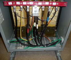
Grounding electrode and grounding electrode conductor — The 2011 NEC defines grounding electrode as “a conducting object through which a direct connection to earth is established,” and the grounding electrode conductor as “a conductor used to connect the system grounded conductor or the equipment to a grounding electrode or to a point on the grounding electrode system.” The purpose of the grounding electrode and grounding electrode conductor is to connect the separately derived system/transformer grounded conductor or equipment to ground (earth), to limit the voltage imposed by line surges and to stabilize the transformer secondary voltage to ground during normal operation (Photo 3).
Section 250.66 and Table 250.66 are used to size the grounding electrode conductor based on the size of the derived ungrounded circuit conductors supplied by the secondary of the transformer; however, because the maximum current in a grounding electrode conductor is limited by the impedance path through the grounding electrode and earth — and is not intended to be part of the effective ground-fault current path — the 12.5% rule does not apply.
Bonding of metal water piping system(s) and exposed structural metal — Section 250.104(D) of the 2011 NEC requires that where a separately derived system/transformer supplies power to an area, the grounded conductor shall be bonded to the nearest available point of the metal water piping system(s) and the exposed building frame structural metal in the area served by the transformer. This bonding jumper connection effectively eliminates any possible difference of potential that can exist between the grounded conductor of the transformer derived source, the metal water piping system(s), and the exposed building frame structural metal. It also provides a ground-fault current path for ground-fault current likely to be imposed on the metal water piping system(s) or exposed building frame structural metal in the area served by the transformer.
Table 250.66 is used to size these bonding jumper conductors based on the size of the derived ungrounded circuit conductors supplied by the secondary of the transformer. Because the metal water piping system(s) or exposed building frame structural metal in the area served by the transformer will predominantly be used as a grounding electrode as identified in 250.30(A)(4), the rules for grounding electrode conductors apply. Therefore, the 12.5% rule does not apply. To prevent objectionable current flow, this bonding jumper conductor connection shall be made at the same point on the separately derived system where the grounding electrode conductor is connected, as stated in 250.104(D).
A separate bonding jumper from the grounded conductor to the metal water piping system(s) and exposed building frame structural metal is not required when either is used as a grounding electrode, as identified in 250.30(A)(4), and if a bonding jumper is installed between the exposed building frame structural metal and metal water piping system in the area served by the transformer.
Supply-side bonding jumper — The 2011 NEC defines supply-side bonding jumper as “a conductor installed on the supply side of a service or within a service equipment enclosure(s), or for a separately derived system, that ensures the required electrical conductivity between the metal parts required to be electrically connected.” Specific to this article, the supply-side bonding jumper is the conductor of the wire type, run with the derived circuit conductors from the source/transformer enclosure to the first system disconnecting means. The objective of the supply-side bonding jumper is to connect the equipment grounding conductors of the transformer derived source to the system bonding jumper/equipment grounding conductor connection, which is required to create an effective ground-fault current path. If a ground fault occurs on the derived ungrounded circuit conductors, ground-fault current will flow from the point of the ground fault on the derived ungrounded circuit conductors to the system bonding jumper/equipment grounding conductor connection by means of the supply-side bonding jumper to the derived source and then back to the origin of the fault. This unintentional ground-fault current flow elevates the current in the transformer primary for ground faults between the derived source of the transformer and the first overcurrent protection device — or facilitates the operation of the transformer secondary overcurrent protection devices if the ground fault is on the load side of these devices.
Table 250.66 is used to size the supply-side bonding jumper based on the size of the derived ungrounded circuit conductors supplied by the secondary of the transformer. The supply-side bonding jumper is part of the ground-fault current path. Therefore, the 12.5% rule does apply.
When the system bonding jumper is not located at the derived source of the separately derived system, the grounded conductor (neutral) serves as part of the supply-side bonding jumper during a ground-fault condition. Thus, in addition to the existing requirements for grounded conductor sizing, the grounded conductor must comply with the same minimum sizing requirements as the supply-side bonding jumper per 250.30(A)(3).
Equipment grounding conductor — The 2011 NEC defines an equipment grounding conductor as “the conductive path(s) installed to connect normally non-current-carrying metal parts of equipment together and to the system grounded conductor or to the grounding electrode conductor, or both.” The purpose of the equipment grounding conductor for the transformer primary circuit is to connect all conductive material that encloses the transformer’s primary ungrounded circuit conductors or electrical equipment, which is required to create an effective ground-fault current path. This path allows unintentional ground-fault current to flow from the point of a ground fault on the transformer primary ungrounded circuit conductors to the transformer metallic enclosure to the building main service or source of the transformer primary circuit and then back to the origin of the fault, facilitating the operation of the transformer primary circuit overcurrent protection devices. The equipment grounding conductors also prevent an objectionable potential above ground (earth) on raceways and equipment enclosures.
Section 250.122 and Table 250.122 are used to size the equipment grounding conductor based on the rating or setting of automatic overcurrent devices in the circuit ahead of electrical raceways, enclosures, and equipment.
The Table below summarizes the components described in this article, applicable 2011 NEC sections, and sizing table headings. It provides component functions and outlines minimum requirements as identified in the NEC related to bonding/grounding for safety of single, solidly grounded, 480V – 208Y/120V, delta-to-wye, 3-phase transformers.

Schamel is the president of Electrical Service Solutions, Inc., Huntington Beach, CA. He can be reached at [email protected].