You're probably familiar with the old-fashioned strings of holiday lights that go out completely if one bulb burns out. Although these lights cause hours of frustration during the holidays, they also provide an excellent example of a series circuit. The individual bulbs that make up the string are connected in series, or one after another. When a voltage is applied across the entire string, a current will flow and the bulbs will light. In a series circuit, the same quantity of current flows through each element in the circuit. If a string consists of 60 bulbs, the applied voltage (120V, for example) is divided equally across each bulb, resulting in 2V per bulb (120V÷60 bulbs). The resistive elements in the bulbs of the series circuit obey Ohm's Law, which states that the voltage across a resistive element equals the resistance of the element times the current flowing through that element (V5R×I).
Series problems
But what happens when a bulb burns out? When the filament breaks, the series circuit now contains an open link. This open link does two things: it causes the current to stop flowing, so the remaining lights go out, and it causes the full 120V to appear across the broken filament. This means that even though the bulbs are designed to operate at 2V, they have to withstand 120V across the broken filament, which is clearly a bad design.
Modern strings of holiday lights avoid the “one bad bulb” problem by using a shorting disk in each bulb that acts as an open circuit at low, or normal, operating voltages, but permanently shorts across the filament when high voltage is impressed across it. An airport runway lighting circuit is another example of a series circuit. Here, the secondary winding of an isolation transformer supplies each bulb. So when a filament burns out, the primary transformer winding maintains the series circuit. But even this design poses a problem.
Too many bad bulbs
Consider again a 60-bulb light string. If shorting disks are provided to complete the circuit after a bulb burns out, what happens if 10 bulbs in the string burn out? The 120V applied to the string is now divided over 50 bulbs instead of 60, resulting in a voltage of 2.4V per bulb (120V÷50 bulbs). This voltage is 20% higher than the design voltage of the bulb, so operating a 60-bulb string of holiday lights with 10 burned out bulbs would shorten the life of the remaining bulbs considerably. Airport runway lighting circuits avoid this problem by using constant current power supplies to supply the series circuit.
Impedance and capacitance
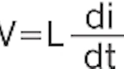
What if a series circuit consists of elements other than resistances? Ohm's Law still applies, but mathematically it changes from a basic algebraic equation to a differential equation. This complication is no cause for panic — it simply means that for an inductance, the voltage (V) across the inductor equals the inductance of the element (L) times the rate at which the current (i) through the inductance changes with time.
As mentioned in the March “Back to Basics” column on capacitors, a circuit containing resistance, inductance, and capacitance is subject to resonance. Resonance is an energy exchange between the inductor's magnetic field and the capacitor's electric field that produces high voltages in the process. Sometimes resonance is a desired condition, such as in a radio receiver where a tuning circuit is designed to be resonant at the carrier frequency of the radio signal received. Other times, resonance is undesirable, as is the case with series capacitors and the inductance of a long transmission line where resonance would cause extremely high and potentially damaging voltages.


