Editor’s note: The following article is based on a white paper written by Dion Neri and Bruce Glushakow that is currently in review as an IEEE transactions paper.
For decades, American transient voltage surge suppressor (TVSS) products have been tested using the 8/20microsec waveform according to ANSI/IEEE C62.41 guidelines. The products designed and manufactured under these guidelines have performed well in the field.
Until 1995, the 8/20microsec waveform was also accepted in virtually all other countries, including those that use the International Electrical Code (IEC). At that time, however, the IEC 61643 family introduced a “Class 1” test for surge protectors installed at service entry locations. In order to meet the impulse current (Iimp) requirements of IEC 61643-1, testing organizations now had to use the 10/350microsec test waveform. The change was based upon the assumption that the 10/350microsec waveform better simulated the parameters of a direct lightning strike, hence making it more relevant in the determination of the effectiveness of surge protective devices (SPDs).
Based upon its proven track record, the IEEE saw no reason to change its SPD testing standards. However, the introduction of the IEC 61643-1 Class 1 test opened a window of opportunity and European manufacturers engage upon a campaign to legitimize the use of this long waveform. Their message was simple: “If direct lightning strikes could only be simulated by a 10/350microsec waveform, then the SPDs produced according to ANSI/IEEE guidelines were an inadequate defense against lightning.”
According to the new testing requirements, the 10/350microsec waveform is to be used for protection against direct lightning currents while the 8/20microsec waveform is useful only for protection against indirect lightning effects.
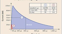
One manufacturer produced a diagram (at right) to show that a 100kA 10/350microsec impulse delivers 125 times as much discharge in amps as a 20kA 8/20microsec pulse. And use of an MOV protector for a 100kA 10/350microsec pulse would require about 2,500kA 8/20microsec MOV capability.
In reality, there’s no ANSI/IEEE-tested, low-voltage SPD on the market rated anywhere near 2,500kA. It’s understood that a TVSS rated at 400kA 8/20microsec is more than sufficient for even the most extreme lightning environments.
Formulas were even presented in a textbook that allegedly proved that an SPD tested with a 20kA 10/350microsec waveform was as much as 20 times more capable than one tested with a 20kA 8/20microsec waveform.
However, in the midst of this debate, SPDs tested with the 8/20microsec waveform continued to be successful in protecting sensitive electronic equipment against the effects of direct lightning strikes all over the world.
The controversy. The 10/350microsec waveform made its debut in IEC 61312-1. Controversy surrounded it even before IEC 61312-1 was adopted. Attempts to forge a consensus for the 10/350microsec parameter in the 1995 TC 81 committee resulted in 78% of 18 voting countries voting in favor of the document. When the lightning parameter was reissued in IEC 61312-3:2000, the percentage dropped to 68% of 19 voting countries.
IEEE C62.41.2-2002 assessed the parameters of first-stroke lightning, including the 350microsec “time to 0.5 peak” defined in IEC 61312 documents, and made the following conclusion:
“The case for ‘high-energy’ surge requirements rests on a consensus based on limited data, a matter of some concern when comparing these ‘requirements’ with the field performance of SPDs designed on the basis of the standards of the IEEE C62 family.”
The following three areas of research prompted investigation:
-
Who or what was the source of the 10/350microsec waveform?
-
Upon what technical data was this waveform based?
-
How well did the 10/350microsec waveform represent the parameters of a direct lightning strike?
What is the 10/350microsec waveform? The 10/350microsec waveform describes two parameters of an impulse of energy. The “10” denotes the amount of time, in microseconds, it takes to achieve 90% of its rise to peak amplitude. The “350” refers to the duration, in microseconds, it takes for the trailing edge to diminish down to 50% of that peak. It’s illustrated in the diagram at right. However, a duration of 350microsec along with a high Ipeak will cause damage in almost all semiconductor based protection devices.
As it turns out, it was the authors of IEC 61312-1 who made the decision to adopt this waveform. IEC Technical Committee TC81 (Lightning Protection) asserted in that standard that the “time to half value” of a typical lightning strike was 350microsec.
Chain of events. The chain of events that led to the widespread acceptance of the 10/350microsec waveform warrants reiterating here. The following facts come from the white paper upon which this article is based:
-
IEC countries use the 10/350microsec waveform for testing SPDs to be installed at service entrance locations in order to meet the impulse current (Iimp) requirements of IEC 61643-1.
-
IEC 61643-1 offers IEC 61312-1 as the only reference for its lightning test parameters. See Annex A on page 143 of 61643-1.
-
IEC 61312-1 bases its lightning current parameters solely on the results of studies published in two issues of an international electrical journal in 1975 and 1980.
The International Council on Large Electric Systems (CIGRE) is a non-governmental international association based in France. It was founded in 1921 to develop the exchange of engineering knowledge and information regarding generation and high-voltage transmission, between engineering personnel and technical specialists around the world.
Despite IEC’s claims to the contrary, CIGRE’s bilingual magazine Electra didn’t include any observations or contributions whatsoever concerning the duration of lightning strokes in 1980.
An issue published in 1975 included a paper authored by Swiss lightning researcher K. Berger that documented results from a lightning measurement station on Mount San Salvatore above Lake Lugano in Switzerland. Particularly relevant is the parameter the author termed the “lightning stroke duration,” which he defined as the time interval between the 2kA point on the front and the point on the tail where the current amplitude has fallen to 50% of its peak value.”
IEC 61312-1 focused specifically on the parameters offered in the article for positive first strokes. TC81 explained their reasoning for this in Annex A of 61312-1: “As a first approach it is assumed that 10% of all flashes are positive and 90% are negative. Despite this low ratio of positive to negative flashes, the positive ones, consisting only of a first stroke and a long duration stroke, determine the maximum values of the parameters I, Q and W/R to be considered. If according to protection level 1, about 99% of all flashes are to be covered, the positive flashes with probabilities below 10% determine the maximum values of peak current I, the charge of the flash Qf, the charge of the short duration strokes Qs, and the specific energy W/R. The values of the corresponding 1% of probabilities of negative flashes are much lower than the values of the 10% probabilities of the positive flashes and may be disregarded for that reason.”
In other words, the authors of IEC 61312-1 determined that they would be “safe” if they used the parameters found by Berger to correspond to the much rarer but nominally longer positive first strokes. It should be noted, however, that the author deemed those results inconclusive.
Studies conducted in the past 30 years have brought those results into question. To begin with, the positive cloud-to-ground flashes included in the study originated from tall towers, not from any mountain peaks without tall structures. That places them into the category of “triggered” lightning. All but one of the flashes noted in the study had an upward propagating leader followed by a downward moving return stroke. IEC 61321-1 falsely stated that the study’s data was representative of the 10% naturally occurring positive first strokes. Triggered lightning of this nature accounts for considerably less than 1% of all lightning.
These findings led the authors of IEC 61312-1 to believe that the Ipeak of positive return strokes was much higher than that of its negative counterparts. However, when the National Lightning Detection Network (NLDN) completed its census of 1.46 million large peak current cloud-to-ground flashes (LPCCGs) of both polarities in the late 90s, which represent 2.46% of the more than 60 million measured flashes, it found “for all values of Imax>75kA, the large negative cloud-to-ground events outnumbered the large positive cloud-to-ground events by considerable margins.”
IEC 61312-1 inferred from Berger that the return-stroke waveform of positive flashes was very different from that of negative flashes. Subsequent research established that the two wave shapes were in fact comparable.
What’s the duration of a lightning stroke? Lightning is perhaps nature’s most elusive phenomena. Despite inherent difficulties involved in studying lightning, recent researchers more or less agree on its parameters:
-
In 2001, J.R. Lucas, author of High Voltage Engineering, noted that for the purpose of surge calculations, only the heavy current flow during the return stroke is important. During this period it has been found that the waveform can be represented by a double exponential of the form: i = I(e-alpha x t – e-beta x t) with wavefront times of 0.5microsec to 10microsec and wavetail times of 30microsec to 200microsec. An average lightning current waveform would have a wavefront of the order of 6microsec and a wavetail of 25microsec.
-
A 5-year study completed by the Korea Electrical Power Corp. that used an LPATS manufactured by Atmospheric Research Systems of USA found that of the strokes measured for the study, 95% had a time to half peak of less than 22microsec. The average time to half peak was 10.82microsec.
-
A study in Japan in 1977 found the average time to half peak to be 40microsec.
-
The National Oceanic & Atmospheric Administration (NOAA) reports that “Each return stroke exhibits a peak current of 5 to 300 kilo amps and has a nominal duration of 20 to 50microsec.”
Where does the IEEE stand? Those who support the concept of the 10/350microsec waveform now believe that the IEEE is moving in the direction of accepting the 10/350microsec waveform.
The IEEE publishes the standards that are in used in environments that contain the largest and most sensitive concentration of electronic devices in the world. C62.45-2002 together with C62.41.1-2002 and C62.41.2-2002 have been issued as the IEEE SPD Trilogy, which comprises 292 pages of technical materials.
After a survey of testing waveforms and procedures that portray the lightning surge environment, the IEEE concluded that the two standard waveforms recommended by IEEE Std C62.41.2-2002 are the 100 kHz ring wave and the 1.2/50microsec to 8/20microsec combination wave, the latter involving two waveforms—one for voltage and the other for current.
Clifford is a design engineer with MCG Surge Protection in Deer Park, N.Y.


